Startline S 424-S 421-S 521-S 524
Operator manual
133
UK
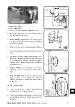
3- upper base plate
4- lower base plate
5- M10X130 screw (nuts and flat washer) no. 4
1.
Fasten the upper plate on the machine frame
and align the holes (fig.40).
2.
Helper HTB21 only:
Place the plate with support
foot (Fig. 40A) on the plate of Fig. 40 aligning
the fastening holes.
3. Place the Helper on the base by aligning the holes.
4. Add the lower plate and fasten with the supplied
screws
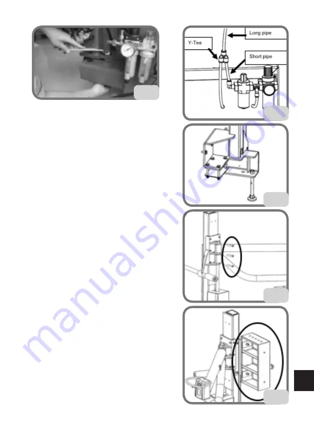
5. Disconnect the tyre changer regulator hose, con-
nect the Y-connector and the hose Ø8 supplied
by connecting it with the Helper regulator.
Connect the Y-connector with the tyre changer
regulator (Fig. 42).
6.
Helper HTB24 only:
Complete the screws
fastening to the vertical sidewall of the frame
(fig.43).
7.
Helper HTB21 only:
Complete the pressing
arms fastening by connecting them with the
cylinder rod and the tool box fastening (figures
44 and 45).
10.1.b. Calibration
1. Lock a wheel on the turntable, take the bead
presser arm into working position.
2. If the arm centring cone does not appear in the
centre of the wheel, turn the fixing screws of the
accessory.
42
41
44
43
45
Summary of Contents for Startline S 421
Page 64: ...64 Startline S 424 S 421 S 521 S 524 Manuale Operatore Montaggio...
Page 77: ...Startline S 424 S 421 S 521 S 524 Manuale Operatore 77 I 18 SCHEMA ELETTRICO GENERALE...
Page 78: ...78 Startline S 424 S 421 S 521 S 524 Manuale Operatore...
Page 79: ...Startline S 424 S 421 S 521 S 524 Manuale Operatore 79 I...
Page 81: ...Startline S 424 S 421 S 521 S 524 Manuale Operatore 81 I Note...
Page 144: ...144 Startline S 424 S 421 S 521 S 524 Operator manual Mounting...
Page 157: ...Startline S 424 S 421 S 521 S 524 Operator manual 157 UK 18 GENERAL WIRING DIAGRAM...
Page 158: ...158 Startline S 424 S 421 S 521 S 524 Operator manual...
Page 159: ...Startline S 424 S 421 S 521 S 524 Operator manual 159 UK...
Page 161: ...Startline S 424 S 421 S 521 S 524 Operator manual 161 UK Notes...
Page 224: ...224 Startline S 424 S 421 S 521 S 524 Manuel Op rateur Montage...
Page 237: ...Startline S 424 S 421 321 S 524 Manuel Op rateur 237 F 18 SCH MA LECTRIQUE G N RAL...
Page 238: ...238 Startline S 424 S 421 S 521 S 524 Manuel Op rateur...
Page 239: ...Startline S 424 S 421 321 S 524 Manuel Op rateur 239 F...
Page 241: ...Startline S 424 S 421 321 S 524 Manuel Op rateur 241 F Notes...
Page 304: ...304 Startline S 424 S 421 S 521 S 524 Bedienungsanleitung Montage...
Page 317: ...Startline S 424 S 421 S 521 S 524 Bedienungsanleitung 317 D 17 ALLGEMEINGER SCHALTPLAN...
Page 318: ...318 Startline S 424 S 421 S 521 S 524 Bedienungsanleitung...
Page 319: ...Startline S 424 S 421 S 521 S 524 Bedienungsanleitung 319 D...
Page 321: ...Startline S 424 S 421 S 521 S 524 Bedienungsanleitung 321 D Anmerkungen...
Page 384: ...384 Startline S 424 S 421 S 521 S 524 Manual Operador Montaje...
Page 397: ...Startline S 424 S 421 S 521 S 524 Manual Operador 397 E 18 ESQUEMA EL CTRICO GENERAL...
Page 398: ...398 Startline S 424 S 421 S 521 S 524 Manual Operador...
Page 399: ...Startline S 424 S 421 S 521 S 524 Manual Operador 399 E...
Page 401: ...Startline S 424 S 421 S 521 S 524 Manual Operador 401 E Notas...

