136
Startline S 424-S 421-S 521-S 524
Operator manual
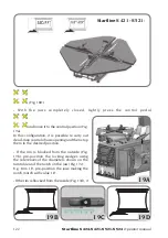
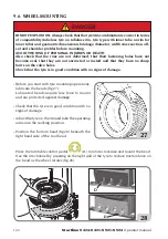
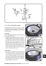
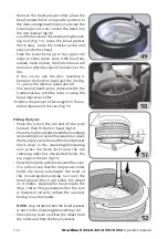
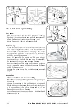
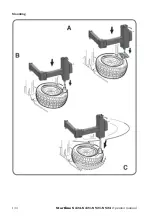
- Remove the bead presser roller, place the
bead presser block in opposite position to
the demounting/mounting tool, activate the
lowering lever so as to insert the bead into
the rim channel (fig.50).
- Load the bead over the demounting/mount-
ing tool (Fig. 50), move the bead presser
block away, press the rotation pedal and
take out the first bead.
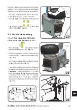
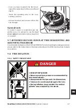
- Take the lower bead up to the upper rim
edge; in some cases, even if the bead has
already been broken, the bottom bead will
remain in place because it has stuck to the
rim.
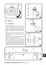
If this occurs, use the disc, inserting it
between the bottom bead and the rim (fig.
51), press the rotation pedal and lift.
- The second bead can be demounted in the
traditional way, with the lever or using the
bead depressor roller.
-Position the presser roller tangent to the ex-
ternal diameter of the rim (Fig. 51).
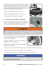
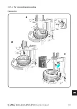
Fitting the tyres
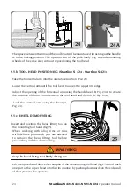
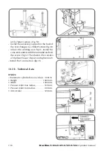
- Place the tyre on the rim and tilt the pole
forward, then fit the first bead (fig.52)
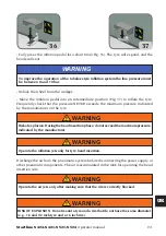
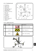
- Place the top bead underneath the mounting/
demounting tool, and at the same time, place
the bead presser roller and the bead presser
block close to the mounting/demounting
tool, press the down lever until the rim
clamping roller has descended below the
top edge of the rim (fig.53).
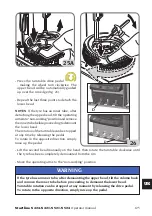
- Press the rotation pedal and mount the cover.
- You will now see that the rim presser roller
holds the bead underneath the head of
the mounting/demounting tool and the
bead presser block will follow the wheel
as it rotates, keeping the bead inside the
drop centre. This guarantees that the tyre
is mounted correctly without the operator
having to use his hands.
NOTE:
stop rotation when the bead presser
is next to the mounting/demounting tool.
- Press the up lever and free the wheel from
the roller and from the bead presser.
51
52
49
50
Summary of Contents for Startline S 421
Page 64: ...64 Startline S 424 S 421 S 521 S 524 Manuale Operatore Montaggio...
Page 77: ...Startline S 424 S 421 S 521 S 524 Manuale Operatore 77 I 18 SCHEMA ELETTRICO GENERALE...
Page 78: ...78 Startline S 424 S 421 S 521 S 524 Manuale Operatore...
Page 79: ...Startline S 424 S 421 S 521 S 524 Manuale Operatore 79 I...
Page 81: ...Startline S 424 S 421 S 521 S 524 Manuale Operatore 81 I Note...
Page 144: ...144 Startline S 424 S 421 S 521 S 524 Operator manual Mounting...
Page 157: ...Startline S 424 S 421 S 521 S 524 Operator manual 157 UK 18 GENERAL WIRING DIAGRAM...
Page 158: ...158 Startline S 424 S 421 S 521 S 524 Operator manual...
Page 159: ...Startline S 424 S 421 S 521 S 524 Operator manual 159 UK...
Page 161: ...Startline S 424 S 421 S 521 S 524 Operator manual 161 UK Notes...
Page 224: ...224 Startline S 424 S 421 S 521 S 524 Manuel Op rateur Montage...
Page 237: ...Startline S 424 S 421 321 S 524 Manuel Op rateur 237 F 18 SCH MA LECTRIQUE G N RAL...
Page 238: ...238 Startline S 424 S 421 S 521 S 524 Manuel Op rateur...
Page 239: ...Startline S 424 S 421 321 S 524 Manuel Op rateur 239 F...
Page 241: ...Startline S 424 S 421 321 S 524 Manuel Op rateur 241 F Notes...
Page 304: ...304 Startline S 424 S 421 S 521 S 524 Bedienungsanleitung Montage...
Page 317: ...Startline S 424 S 421 S 521 S 524 Bedienungsanleitung 317 D 17 ALLGEMEINGER SCHALTPLAN...
Page 318: ...318 Startline S 424 S 421 S 521 S 524 Bedienungsanleitung...
Page 319: ...Startline S 424 S 421 S 521 S 524 Bedienungsanleitung 319 D...
Page 321: ...Startline S 424 S 421 S 521 S 524 Bedienungsanleitung 321 D Anmerkungen...
Page 384: ...384 Startline S 424 S 421 S 521 S 524 Manual Operador Montaje...
Page 397: ...Startline S 424 S 421 S 521 S 524 Manual Operador 397 E 18 ESQUEMA EL CTRICO GENERAL...
Page 398: ...398 Startline S 424 S 421 S 521 S 524 Manual Operador...
Page 399: ...Startline S 424 S 421 S 521 S 524 Manual Operador 399 E...
Page 401: ...Startline S 424 S 421 S 521 S 524 Manual Operador 401 E Notas...

