98
Startline S 424-S 421-S 521-S 524
Operator manual
ensure that the voltage drop under full load does not
exceed 4% (10% during
start-up) of the rated voltage value specified on the plate
- The user must:
• fit a power plug in compliance with current regulations
on the power supply lead;
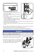
• connect the machine to its own electrical connection
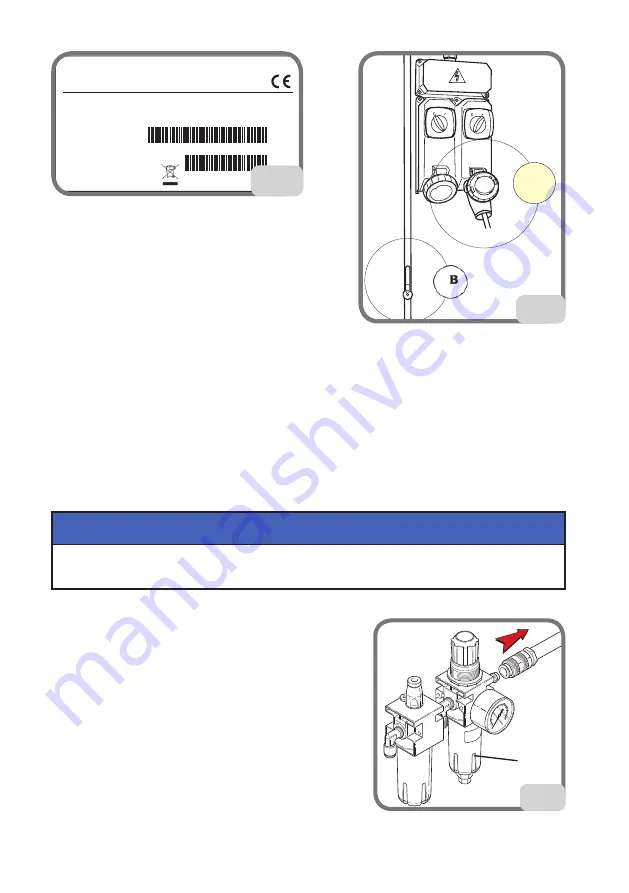
- A, Fig. 2 - equipped with a differential automatic
circuit breaker with 30mA sensitivity;
• install protection fuses on the power line that are suitably sized in accordance with the indications
provided on the machine data plate (Fig.1);
• connect the machine to an industrial socket; the machine must not be connected to domestic
sockets.
Make sure that the available pressure and performance of the compressed air system are
compatible with what is necessary for correct machine operation - see
the section “Technical data”. For the correct operation of the machine, the pneumatic
supply line must provide a pressure range from a minimum of 8 bar to a maximum of 16 bar.
For correct equipment operation, the air produced must be suitably treated (not
above 5/4/4 according to standard ISO 8573-1).
WARNING
Check that the lubrication cup (B, Fig. 2a contains
lubricating oil; top up is necessary. Use SAE20 oil.
The pneumatic supply inlet point, in the workshop
line, must be equipped with a pneumatic supply
shut-off valve, placed upstream the filter/regulator
unit supplied with the machine (B Fig. 2a).
2
A
B
2a
ISO9001
Code
Serial N.
X-XXXXXXXX/XX - XX
XXXXXXXXX
QUAL. SYS. CERTIFIED
ANNO DI COSTRUZIONE /
MANUFACTURED
Mod.
V
A
kW
Hz
Ph
bar/psi
1
Summary of Contents for Startline S 421
Page 64: ...64 Startline S 424 S 421 S 521 S 524 Manuale Operatore Montaggio...
Page 77: ...Startline S 424 S 421 S 521 S 524 Manuale Operatore 77 I 18 SCHEMA ELETTRICO GENERALE...
Page 78: ...78 Startline S 424 S 421 S 521 S 524 Manuale Operatore...
Page 79: ...Startline S 424 S 421 S 521 S 524 Manuale Operatore 79 I...
Page 81: ...Startline S 424 S 421 S 521 S 524 Manuale Operatore 81 I Note...
Page 144: ...144 Startline S 424 S 421 S 521 S 524 Operator manual Mounting...
Page 157: ...Startline S 424 S 421 S 521 S 524 Operator manual 157 UK 18 GENERAL WIRING DIAGRAM...
Page 158: ...158 Startline S 424 S 421 S 521 S 524 Operator manual...
Page 159: ...Startline S 424 S 421 S 521 S 524 Operator manual 159 UK...
Page 161: ...Startline S 424 S 421 S 521 S 524 Operator manual 161 UK Notes...
Page 224: ...224 Startline S 424 S 421 S 521 S 524 Manuel Op rateur Montage...
Page 237: ...Startline S 424 S 421 321 S 524 Manuel Op rateur 237 F 18 SCH MA LECTRIQUE G N RAL...
Page 238: ...238 Startline S 424 S 421 S 521 S 524 Manuel Op rateur...
Page 239: ...Startline S 424 S 421 321 S 524 Manuel Op rateur 239 F...
Page 241: ...Startline S 424 S 421 321 S 524 Manuel Op rateur 241 F Notes...
Page 304: ...304 Startline S 424 S 421 S 521 S 524 Bedienungsanleitung Montage...
Page 317: ...Startline S 424 S 421 S 521 S 524 Bedienungsanleitung 317 D 17 ALLGEMEINGER SCHALTPLAN...
Page 318: ...318 Startline S 424 S 421 S 521 S 524 Bedienungsanleitung...
Page 319: ...Startline S 424 S 421 S 521 S 524 Bedienungsanleitung 319 D...
Page 321: ...Startline S 424 S 421 S 521 S 524 Bedienungsanleitung 321 D Anmerkungen...
Page 384: ...384 Startline S 424 S 421 S 521 S 524 Manual Operador Montaje...
Page 397: ...Startline S 424 S 421 S 521 S 524 Manual Operador 397 E 18 ESQUEMA EL CTRICO GENERAL...
Page 398: ...398 Startline S 424 S 421 S 521 S 524 Manual Operador...
Page 399: ...Startline S 424 S 421 S 521 S 524 Manual Operador 399 E...
Page 401: ...Startline S 424 S 421 S 521 S 524 Manual Operador 401 E Notas...

