background image

Unvented Cast Iron Gas Stoves

25

3-90-58D6002

Monessen • Concorde VF Installation Manual_R11 • 02/17

Requirements for the Commonwealth of 

Massachusetts

This  product  must  be  installed  by  a  licensed  plumber  or 

gas  fitter  when  installed  within  the  Commonwealth  of 

Massachusetts.

Note Regarding Vented Products

Flex line installation must not exceed 36 inches and must 

have a T shutoff valve.
Any residence with a direct vent product must have a CO 

detector installed in the residence.
Installation of the fireplace or vented gas log in the State 

of Massachusetts requires the damper to be permanently 

removed or welded in the fully open position.
In addition, neither a naturally vented gas log nor a vent-free 

product may be installed in a bedroom or bathroom in the 

State of Massachusetts.
All gas fitting and installation of this heater shall only be done 

by a licensed gas fitter or licensed plumber.
For all side wall horizontally vented gas fueled equipment 

installed in every dwelling, building or structure used in whole 

or in part for residential purposes, including those owned or 

operated  by  the  Commonwealth  and  where  the  side  wall 

exhaust vent termination is less than seven (7) feet above 

finished grade in the area of the venting, including but not 

limited  to  decks  and  porches,  the  following  requirements 

shall be satisfied:

Installation of Carbon Monoxide Detectors

At the time of installation of the side wall horizontal vented 

gas fueled equipment, the installing plumber or gas fitter shall 

observe that a hard wired carbon monoxide detector with an 

alarm  is installed on each additional level of the dwelling, 

building  or  structure  served  by  the  side  wall  horizontal 

vented gas fueled equipment. It shall be the responsibility 

of  the  property  owner  to  secure  the  services  of  qualified 

licensed professionals for the installation of hard wired carbon 

monoxide detectors.
In the event that the side wall horizontally vented gas fueled 

equipment is installed in a crawl space or an attic, the hard 

wired carbon monoxide detector with alarm and battery back-

up may be installed on the next adjacent floor level.
In the event that the requirements of this subdivision can not 

be met at the time of completion of installation, the owner shall 

have a period of thirty (30) days to comply with the above 

requirements; provided, however, that during said thirty (30) 

day period, a battery operated carbon monoxide detector with 

an alarm shall be installed.

Approved Carbon Monoxide Detectors

Each carbon monoxide detector as required in accordance 

with the above provisions shall comply with NFPA 720 and 

ANSI/UL 2034 listed and IAS certified.

Signage

A metal or plastic identification plate shall be permanently 

mounted to the exterior of the building at a minimum height 

of eight (8) feet above grade directly in line with the exhaust 

vent terminal for the horizontally vented gas fueled heating 

appliance or equipment. The sign shall read, in print size no 

less than one-half (1/2) inch in size, 

“GAS VENT DIRECTLY 

BELOW, KEEP CLEAR OF ALL OBSTRUCTIONS”.
Inspection

The state or local gas inspector of the side wall horizontally 

vented gas fueled equipment shall not approve the installation 

unless,  upon  inspection,  the  inspector  observes  carbon 

monoxide detectors and signage installed in accordance with 

the provisions of 248 CMR 5.08(2)(a)1 through 4.

Exemptions

The following equipment is exempt from 248 CMR 5.08(2)

(a)1 through 4:
•  The equipment listed in Chapter 10 entitled “Equipment 

Not Required To Be Vented” in the most current edition 

of NFPA 54 as adopted by the Board; and

•  Product Approved side wall horizontally vented gas fueled 

equipment installed in a room or structure separate from 

the dwelling, building or structure used in whole or in part 

for residential purposes.

Manufacturer Requirements:

Gas Equipment Venting System Provided

When  the  manufacturer  of  Product Approved  side  wall 

horizontally vented gas equipment provides a venting system 

design or venting system components with the equipment, 

the instructions provided by the manufacturer for installation 

of the equipment and the venting system shall include:
•  Detailed  instructions  for  the  installation  of  the  venting 

system design or the venting system components; and

•  A  complete  parts  list  for  the  venting  system  design  or 

venting system.

Gas Equipment Venting System NOT Provided

When  the  manufacturer  of  a  Product Approved  side  wall 

horizontally vented gas fueled equipment does not provide 

the parts for venting the flue gases, but identifies “special 

venting  systems”,  the  following  requirements  shall  be 

satisfied by the manufacturer:
•  The referenced “special venting system” instructions shall 

be included with the appliance or equipment installation 

instructions; and

•  The “special venting systems” shall be Product Approved 

by the Board, and the instructions for that system shall 

include a parts list and detailed installation instructions.

A copy of all installation instructions for all Product Approved 

side wall horizontally vented gas fueled equipment, all venting 

instructions, all parts lists for venting instructions, and/or all 

venting design instructions shall remain with the appliance 

or equipment at the completion of the installation.

Summary of Contents for Double Door VFCS30DNV

Page 1: ... Operation INSTALLER Leave this manual with party responsible for use and operation OWNER Retain this manual for future reference Call your dealer for questions on Installation Operation or Service If the information in this manual is not followed exactly a fire or explosion may result causing property damage personal injury or loss of life Do not store or use gasoline or other flammable vapors an...

Page 2: ...STALLATION OPERATING INSTRUCTIONS BEFORE USING APPLIANCE Thank you and congratulations on your purchase of a Monessen stove IMPORTANT Read all instructions and warnings carefully before starting installation Failure to follow these instructions may result in a possible fire hazard and will void the warranty Log and Rock Wool Placement 14 Rock Wool Placement 14 CSVF30 VFCS30 Log Placement 15 Flame ...

Page 3: ... for proper installation 13 Avoid any drafts that alter burner flame patterns Do not allow fans to blow directly into fireplace Do not place a blower inside burn area of firebox Ceiling fans may create drafts that alter burner flame patterns Sooting and improper burning will occur 14 Caution Candles incense oil lamps etc produce combustion by products including soot Vent free appliances will not f...

Page 4: ...e possibly causing headaches or eye or lung irritation This is a normal and temporary occurrence The initial break in operation should last two to three hours with the burner at the highest setting Provide maximum ventilation by opening windows or doors to allow odors to dissipate Any odors remaining after this initial break in period will be slight and will disappear with continued use 21 Input r...

Page 5: ...ermal Generator The millivolt gas log pilot is fitted with a millivolt thermopile generator to provide power for remote activation NOTE An external regulator is required to reduce supply pressure to a maximum of 10 5 w c on Natural Gas systems operating at higher pressure NOTE An external regulator is required to reduce supply pressure to a maximum of 13 0 w c for LP systems Gas Pressures Natural ...

Page 6: ...ke sure you have received all parts Check your packing list to verify that all listed parts have been received You should have the following Cast Iron Stove with Burner Assembly Installation Operating Instructions Ceramic Fiber Logs Touch up Paint Millivolt controlled heater designed to be operated with optional devices for ON OFF functions Hand Held Remote with Manual Receiver Wall Switch with 15...

Page 7: ...Unvented Cast Iron Gas Stoves 7 3 90 58D6002 Monessen Concorde VF Installation Manual_R11 02 17 Stove Dimensions A C B 586002 CSVF dims D Figure 3 Ref CSVF30S VFCS30D A 26C v B 28Z x C 19C v D 23C v ...

Page 8: ...wood flooring the appliance shall be installed on a metal wood or noncombustible material panel extending full width and depth of the appliance WARNING D Minimum to Either Side Wall E Minimum A ST1167 side ceiling clearances Front View Ceiling Mantel Side Wall F Minimum 36 in Front C B ST1168 front rear clearances Side View Ceiling G G ST1169 corner clearances Corner Installation Figure 4 Minimum ...

Page 9: ...l_R11 02 17 Clearances to Combustibles Cont NOTE Maintain minimum side and back clearances when placing stove in alcove ON OFF A C B ST1171 alcove clearances Figure 5 Alcove Installation Tested Minimum Alcove Clearances Height From Hearth Width Depth Model A B C CSVF30 VFCS30 52 34 36 ...

Page 10: ... 5 Remove log box from inside of unit Figure 8 6 Remove 4 shipping brackets located at the leveler screw of each leg Lift unit off pallet NOTE You will need at least two 2 strong people to lift unit off of pallet Installation Figure 6 Remove plastic bag from unit ON OFF LOGS ST1172 stove on pallet Plastic Bag Plastic Banding Pallet PIL OT OF F RE MO TE CO NT RO L L O G S ST1173 remove hearth door ...

Page 11: ...ystem must be sized to provide minimum inlet pressure Listed on Data Plate at the maximum flow rate BTU hr Undue pressure loss will occur if the pipe is too small A manual shutoff valve must be installed upstream of the appliance Union tee and plugged 1 8 NPT pressure tapping point should be installed upstream of the appliance Figure 9 A sediment trap should be installed upstream to prevent moistu...

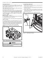
Page 12: ...essure against data plates or manual Turn captured slotted screw counter clockwise 2 or 3 turns and then place tubing to pressure gauge over test point Use test point OUT closest to control knob After taking pressure reading be sure and turn captured screw clockwise firmly to re seal Do not over torque Check for gas leaks NOTE Remove control panel to access gas valve Connect Remote Receiver 1 Remo...

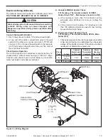
Page 13: ...urner should turn ON a If the reading is more than 100 millivolts and the automatic valve still does not come on replace the control b If the closed circuit reading A reading is less than 100 millivolts determine cause for low reading proceed to Section B below B Thermopile Output Reading Check B Reading Thermostat contacts OPEN Main burner OFF 1 Check gas pressure to the unit If gas pressure is w...

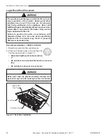
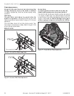
Page 14: ...n of this heater Sooting and other problems may result if the logs are not properly and firmly positioned in the appliance Never add additional logs or embellishments such as pine cones vermiculite or rock wool to the heater Only use the logs supplied with the unit Failure to position the parts in accordance with diagrams below or to use only parts specifically approved for this heater may result ...

Page 15: ... the logs is critical to the safe and clean operation of this heater Sooting and other problems may result if the logs are not properly and firmly positioned in the appliance Never add additional logs or embellishments such as pine cones vermiculite or rock wool to the heater Only use the logs supplied with the unit Failure to position the parts in accordance with diagrams below or to use only par...

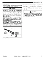
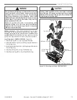
Page 16: ...o Figure 16 for incorrect shape of pilot flame Millivolt Control Burner Flame In normal operation at full rate after 15 minutes the following flame appearances should be observed The left and right rear flames should be yellow and extend 1 2 above middle logs The yellow flames should not contact the logs There should be glowing embers on the front surface of the middle log NOTE The flames and embe...

Page 17: ... working properly refer to Match Lighting instructions on Page 20 B BEFORE OPERATING smell all around the appliance area for gas Be sure to smell next to the floor because some gas is heavier than air and will settle on the floor WHAT TO DO IF YOU SMELL GAS Turn off all gas to the appliance Open windows Do not attempt to light any appliance Do not touch any electric switch do not use any phone in ...

Page 18: ...t time it will be necessary to press in the control knob for 30 seconds to allow air to bleed out of the gas piping TO TURN OFF GAS TO HEATER Pilot Control Cover Plate for Millivolt ST1178 control cover plate Hi Lo Control Ignitor Pilot Control OFF ON ST1179 on off switch On Off Switch Located on Side of Stove 7 With the control knob pushed in push in and release the piezo ignitor button to light ...

Page 19: ...nal case should be dusted and wiped with a moist cloth 1 Open stove door Remove any items necessary for easy access to the pilot for example logs screens etc 2 Follow appropriate lighting instructions found previously Instead of pushing and releasing the piezo button light a match and hold the flame to the end of the pilot and ignite the pilot 3 After control knob has been released and pilot stays...

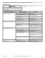
Page 20: ...produces unwanted odors A Appliance burning vapors from paint hair spray glues etc Ventilate room Stop using odor causing products while heater is running B Gas leak Locate and correct all leaks C Initial burn off Ventilate room and turn unit on high until odor is gone Odor should be gone after 6 hours of continuous use Appliance shuts off during use A Not enough fresh air is available for ODS pil...

Page 21: ...urner orifice is clogged Clean burner or replace burner orifice Slight smoke or odor during initial operation A Burner orifice is clogged or damaged Clean burner or replace burner orifice B Burner is damaged Replace burner C Gas regulator defective Replace gas regulator Logs appear to smoke after initial oper ation A Vapors from paint or curing process of logs Problem will stop after a few hours o...

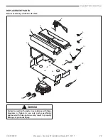
Page 22: ...EPLACEMENT PARTS Burner assembly CSVF30 VFCS30 3 4 5 6 7 8 9 10 11 12 1 13 14 15 2 586002 CSVF VFCS 30 parts Failure to position the parts in accordance with these diagrams or failure to use only parts specifically approved with this appliance may result in property damage or personal injury WARNING ...

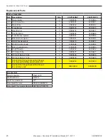
Page 23: ...Injector 1 58D0061 62D3005 9 ODS Pilot Assembly 1 14D0473 14D0477 10 On Off Control Knob 1 43D0094 43D0094 11 Hi Lo Control Knob 1 43D0095 43D0095 12 On Off Switch 1 32D0232 32D0232 13 VF Valve Tube 1 58D0427 58D0427 14 VF Front Burner Tube 1 58D0428 58D0428 15 VF Front Burner Tube 1 58D0429 58D0429 Control Door Hinge Bracket Not Shown For units with starting serial number HF 1 58D0263 58D0263 Con...

Page 24: ...S30 Logs Ref Description Qty Part Number 1 Back Log 1 58D1901 2 Bottom Left Log 1 58D1902 3 Bottom Right Log 1 58D1903 4 Left Top Log 1 58D1904 5 Right Top Log 1 58D1905 Failure to position the parts in accordance with these diagrams or failure to use only parts specifically approved with this appliance may result in property damage or personal injury WARNING ...

Page 25: ...ide detector as required in accordance with the above provisions shall comply with NFPA 720 and ANSI UL 2034 listed and IAS certified Signage A metal or plastic identification plate shall be permanently mounted to the exterior of the building at a minimum height of eight 8 feet above grade directly in line with the exhaust vent terminal for the horizontally vented gas fueled heating appliance or e...

Page 26: ...e center shipping damage damage from improper use or neglect installation damage damage from unauthorized service incidental or consequential damage or negative pressure caused by mechanical systems such as furnaces fans clothes dryers etc TERMS This warranty shall be void if the appliance is not installed a by qualified installer in accordance with the installation instructions provided with the ...

Page 27: ...Unvented Cast Iron Gas Stoves 27 3 90 58D6002 Monessen Concorde VF Installation Manual_R11 02 17 ...

Page 28: ...28 3 90 58D6002 Monessen Concorde VF Installation Manual_R11 02 17 352 Mountain House Road Halifax Pa 17032 www monessenhearth com ...

Reviews: