


HBDV7 Series Direct Vent Gas Fireplace
54D8000
9
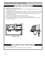
oPeRAtING INStRuCtIoNS - MIllIVolt
PILOT
O
FF
P
IL
O
T
ON
FP1935
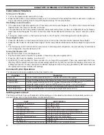
control knob pilot
Continued on next page
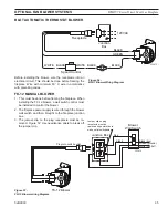
APPRoVeD leAK teStING MetHoD
You may check for gas leaks with the following methods
only:
• Soap and water solution
• An approved leak testing spray
• Electronic sniffer
If using a soap and water
solution to test for leaks,
Do Not spray solution onto
control body.
W
ARNING
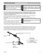
NOTE: Remove any excessive pipe
compound from the connections.
Excessive pipe compound can set off
electronic sniffers.
the control has an interlock device that does not allow the lighting of the fireplace
up to the moment the safety device of the flame has not interrupted the gas flow.
After that period of time (when the magnet is closed), it is possible to start the
lighting operation.
the gas control knob is designed to be operated by hand. Do Not use any tools
during this operation. Damaged knobs may result in serious injury.
W
ARNING
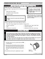
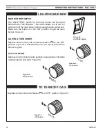
1. Depress and turn knob counterclockwise
to pilot position.
. Depress fully and hold pilot gas knob. Depress
piezo igniter as many times as needed to ignite pilot.
Keep knob fully depressed for a few seconds.
Release and check that pilot continues to
burn.
If the pilot does not stay lit, repeat steps 1 and .
lIGHtING PIlot
Figure 47 -
Pilot Position
Check for gas leaks in each of the following locations:
• Pipe from the gas supply line connection to the gas valve
• Burner connections
• Field made joints / gas shutoff valve
• Pilot
• Factory made joints
• Each joint or connection
• All joints on valve and control body
Never check for gas leak with open
flame!
DANG
e
R
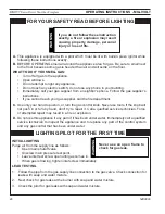
lIGHtING PIlot FoR tHe FIRSt tIMe


