background image

12

424WBST Designer Woodburning Fireplaces

87D1506

 Installing the Chimney System

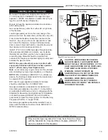
Start by attaching the first chimney section to the collar 
on top of the fireplace.


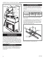
Install the pipe as pictured in Figure 16. When  you 
get a good lock, you will hear the pipe clearly snap 
together. Once sections are snap-locked in place, it is 
extremely difficult to get them apart. 

Make sure the 

pipe is firmly snapped and locked together as each 
pipe section is mounted.

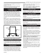
When installing elbows, only outer pipe will snap- 
lock.  Middle pipes simply slide into position. Be sure 
to always attach straps on upper elbow to a structural 
framing member. (Fig. 17)
Continue installing the pipe as required until pipe is 
installed up through the ceiling. At this point, you must 
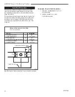
install a firestop spacer. Refer to Figure 18 for appropri-
ate spacer orientation.

Installing the Firestop Spacer 

in the Ceiling Hole

A firestop spacer is used to keep pipe spaced properly 
and required for safety.
Nail the firestop spacer (at each corner) to the framing 
members of the ceiling hole. 

NOTe: 

 A firestop spacer 

is not required at the roof.
Hole sizes listed in Figure 12 for angled firestop spac-
ers provide minimum required air space to chimney 
pipe for ceiling thickness up to 8" (203 mm).  When 
combined thickness of ceiling material, ceiling joists and 
flooring material exceeds 8" (203 mm), adjustments 
must be made in framing to assure that minimum air 
spaces to chimney are maintained.

Proper Firestop Spacer Installation

Figure 18 shows different installation procedures for  
both an area that 

is

 an attic and  an area that 

is not

 an 

attic.
If the area above the ceil-
ing

 is not 

an attic, posi-

tion the firestop spacer 
with the flange on the ceil-
ing side and the angled 
portion extending up into 
the hole.
If the area above the 
ceiling 

is

 an attic, position 

the firestop spacer with 
the flange on the top of 
the framed hole and the 
angled portion extending 
down into the hole.

FP711

Fig. 16 

 Install pipe, listening for the snap-lock to fasten.

UP

Lance

Hem

Pipe Rim

Pipe 

  Rim

WF711

STR/CVR

5/28/98

Pipe Section

Fig. 17 

 Attach straps to a structural framing member.

FP270/271

FP270/271

CR Series

2/19/99   djt

elbow Strap

Support Structure

Elbow Strap

(must be tight)

Ceiling 

Hole Fram-

ing

Angle Firestop

Chimney Support 

Strap

(must be tight)

Angled Strap

FP593

SR/C

11/20/97

Attic Installation

Ceiling Installation

Fig. 18 

 Installing firestop spacer.

FP593

Nails (4)

Firestop 

Spacer

Joist

Joist

Firestop 

Spacer

Nails (4)

NOTe:

 If the attic insulation shield is used, the 

firestop is not required in the attic installation.

Summary of Contents for WOODBURNING FIREPLACE 424WBST

Page 1: ...er Woodburning Fireplace For use in U S Canada Underwriter s Laboratories Report No MH7603 DO NOT DISCARD THIS MANUAL Retain for future use 87D1506 12 09 Rev 2 Homeowner s Installation and Operating Manual 342 COVER ...

Page 2: ... combination or assembly with a Monessen Fire places fireplace system notwithstanding any independent testing laboratory or other third party approval of such component parts or ac cessory Any such action may possibly cause a fire hazard Consult local building codes to ensure that you are in compliance before installing the fireplace Fireplaces must be vented to the out of doors Do not obstruct or...

Page 3: ... 24 Total Unit Width Framing Width Will be 24 Minus 2 x Drywall Thickness 1856M 464 mm STR33 STR36 STR42 A 33 36 42 838mm 914mm 1067mm B 37 40 46 940mm 1016mm 1168mm C 1856O 20 23 470mm 508mm 584mm D 49 6 49 6 53 6 1267mm 1267mm 1368mm E 52 6M 52 6M 56 6M 1340mm 1340mm 1442mm F 11 11 1356O 279mm 279mm 343mm G 8 8 11 203mm 203mm 279mm J 26 6M 29 6QE 35 6QE 680mm 741mm 894mm 8 203 mm Dia 12 305 mm 5...

Page 4: ... B 424WBST 29 17Z 737 mm 435 mm FP1545 Fig 3a Hearth dimensions FP701a STR Parts ID Gas Line Access Outer Dome Outside Air Access Ledge Brackets Header Standoffs Flue Damper Control Inside Flue Collar Outer Collar Gas Line Knock out Both Sides Brick liner on Sides and Hearth Air Inlet Hearth Wood Grate Firebox Metal Safety Strips shown not in place 1 2 or 3 Pieces Outside Air Control ...

Page 5: ...ace and chase parts identification FP704 STR from FP528 7 28 98 Termination Cap Storm Collar Pan Flashing Draftstop Finish Wall Batt Insulation cut out around firestop Firestop Ceiling Level Outer Dome Refer to Figures 21 and 26 for clearance information Ledge Brackets Nailing Flange Gas Access both sides Outside Air Cover Plate Surround Screen Grate Firebox Outside Air Control ...

Page 6: ...he chimney exit 424WBST Maximum 90 0 Minimum Without Elbows 15 6 With 2 Elbows 17 6 With 4 Elbows 21 0 B Do not use more than 4 elbows per chimney Attach the straps of the return top elbow to a structural framing member The offset first elbow of any pair does not have straps FP720 C The chimney cannot be more than 30 45 in Canada from the vertical plane in any installation D The maximum length of ...

Page 7: ... the roof is 10 3 m or less the top of the chimney must be at least 2 610 mm above the peak of the roof but never less than 3 914 mm in height above the highest point where it passes through the roof 2 If a horizontal distance from the chimney to the peak of the roof is more than 10 3 m a chimney height reference point is established on the surface of the roof a distance of 10 3 m from the chimney...

Page 8: ... very thin gap CAUTION WHEN INSTALLING A FIREPLACE IN AN INSULATED ENCLOSURE BE SURE ALL REQUIRED AIR SPACES ARE MAINTAINED Page 14 Fig 20 Installation Chimney Supports The chimney system is supported by the fireplace for vertical chimney heights less than 20 6 m above the hearth Chimney supports are required if the vertical height exceeds 20 6 m Locate chimney supports at ceiling holes or other s...

Page 9: ... The 424WBST model uses MHSC SK8 2 wall chimney systems Straight Up Chimney Installation To locate the centerline of the flue put the fireplace in final position and place a plumb bob from the ceiling to the center of the fireplace flue collar Mark this spot on the ceiling Draw a line through that mark to either side of the firebox and indicate dimension X to locate the side wall framing Fig 10 Be...

Page 10: ...r that is the same size as the ceiling joists this is a requirement at attic level The following table gives firestop spacer model num bers FP707 STR CVR LOCATE CENTER LINE 6 1 98 STR 33 19 483mm STR36 CVR36 205 O 521mm STR42 CVR42 235 O 597mm MODEL X 2056O 521 mm Fig 10 Locate centerline of chimney with plumb line FP707 Actual Centerpoint Chimney Centerline Side of STR Plumb Line Plumb Bob Imagin...

Page 11: ... fireplace are noncombustible Eight 8 nailing flanges are supplied with the fireplace found on the fireplace hearth To level the box and secure it firmly in place remove the nailing flanges from the hearth and install at the sides of the fireplace as shown in Figure 14 Outside Air Kit An outside air kit damper is installed in 424WBST Fire places If desired or if local codes mandate the use of an a...

Page 12: ... air space to chimney pipe for ceiling thickness up to 8 203 mm When combined thickness of ceiling material ceiling joists and flooring material exceeds 8 203 mm adjustments must be made in framing to assure that minimum air spaces to chimney are maintained Proper Firestop Spacer Installation Figure 18 shows different installation procedures for both an area that is an attic and an area that is no...

Page 13: ...le It is good practice to use fram ing lumber that is the same size as the rafters Install the frame securely because the chimney top and flash ing anchored to the frame must be able to withstand heavy winds Firestop spacers are not available for nor are they re quired on vertical walls DO NOT put any sealant around the area where the outer pipe slides through the firestop spacer If you seal this ...

Page 14: ...eplace surround Black painted area Fig 20 Finish Wall Finish the wall with material of your choice Do not install a combustible mantel shelf less than 12 305 mm above the front opening Do not install a mantel face plate less than 6 159 mm from top of fireplace opening Fig 21 If a combustible material is used below a flat mantel shelf consult your local building codes for minimum clearance from top...

Page 15: ...m Max 1 2 12 305mm Min 12 305mm Max 6 159mm Min FP721 Fig 21 Fireplace surround flush with finished wall Mantel Clearance No Noncombustible Facing Material Finished Wall Standoff 2 x 4 Stud Noncombustible Mate rial Header Ledge Bracket Fireplace Front Fireplace Opening Minimum width from top of sur round to bottom of screen rail Combustible Mantel and Trim Combustible Mantel and Trim Standoff Fini...

Page 16: ...40 with the same wall clearances specified for the SP40 Rt must 1 85 minimum Examples of wall shield insulation 1 Manville CERAFORM 126 K 27 1 2 inches thick 2 MHSC EH2416 K 458 1 inch thick required FP723 Fig 23 Minimum firebox dimensions from combustible materials FP723 STR CVR Side Wall clearances 6 21 98 A A B B C C C D Perpendicular Side Wall Parallel Side Wall Minimum Dimensions to Side Wall...

Page 17: ... 018 minimum sheet metal to protect hearth extension material Fig 24 Secure the hearth extension to the floor to prevent shifting using trim molding or other similar means at three 3 outer edges Seal crack between the fireplace hearth and hearth extension with a noncombustible material Figs 24 and 26 Minimum Wall Clearances WITH Noncombustible Surround Facing WITHOUT Noncombustible Surround Facing...

Page 18: ... of listed thickness K of listed material per inch material Example for Common Brick T new 5 0 0 458 x 0 50 in 5 46 in new required thickness 0 4YPE FLOOR DJT Safety Strips Must be Over lapped 1 2 Min Minimum Insulation Value R 0 94 1 4 Min Thickness Combustible Floor Noncombustible Material 7Z x Max Thickness Seal Cracks Between Fireplace and Hearth Extension with Noncombustible Material Noncombu...

Page 19: ... in a fireplace NOTE When installing an ANSI Z21 11 2 ventless ap pliance the finishing material used for the mantel must be rated at 250 F or greater BTU input of a gas appliance installed in fireplace should be rated less than 100 000 BTU Hr Gas pipe installation is intended for connection to a decorative gas appliance only when 1 incorporating an automatic shutoff device and 2 complying with th...

Page 20: ...Damper Handle 7548170 3 Damper Handle Push Nut 7512903 4 Screen Rod Assembly two per fireplace 3030126 5 Screen Assembly four per fireplace 7554338 6 Screen Pulls four per fireplace 5584139 7a Firebrick Hearth 3102103 7b Firebrick Side Ashlip two per fireplace 3102102 7c Firebrick Side two per fireplace 9079147 7d Side Filler four per fireplace 3079148 8 Top Brick Retainers four per fireplace 3079...

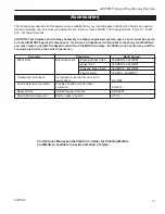
Page 21: ...re available from your local Monessen distributor Should you need ad ditional information beyond what your distributor can furnish contact MHSC 149 Cleveland Drive Paris KY 40361 Attn Technical Services CAUTION This fireplace and chimney assembly is a highly engineered system and as such must be operat ed only with MHSC approved components If you use an unapproved component to make any modificatio...

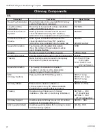
Page 22: ...ons Extends Square Termination on steep pitched roofs 202036 Flashing Metal finishing required around Contemporary 8 6 12 with 8 flue Termination to prevent rain leakage 0 6 12 pitch 8 12 12 with 8 flue 6 12 12 12 pitch Square Termination Top housing of simulated brick pattern T20B available in red tan or white Appropriate adapter required Flashing included SK8 Pipe used to build 8 SK8 flue system...

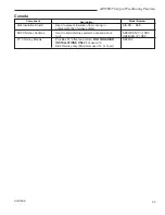
Page 23: ...SK SK8 contact with the chimney system SK8 Chimney Sections Used to build chimney systems exposed above SK818CAN 1 SK8 roof SK84CAN 4 SK8 45 Chimney Elbows Provides 45 offset and return For Canadian SK845 2 installations only For use with SK8 chimney only Maximum use of 2 or 1pair Canada Model Number Description Component ...

Page 24: ...affect safe operation We do not warrant this fireplace to be in compliance with your local building code Building codes vary greatly throughout the country and you should determine whether your local building code contains restrictions on the use of this fireplace before you purchase it Blowers or fans which are warranted separately Heat loss due to the passage of heat or air through or around the...

Reviews: