SR3 Type 1 Technical Manual
TSP005.doc Issue 5.0 – Jan 2005
Money Controls 2005. All rights reserved.
Page 25 of 50
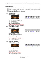
17. Sorter Drivers
Figure 10: Sort Output Connector Details
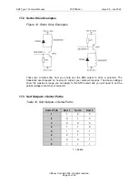
17.1 Sorter Drive Circuit
The sorter output on SR3 is just a low current drive and will not drive a solenoid directly. It
was designed to source or sink a limited current and so it can be connected directly to the
base of the transistor being used to drive the solenoid.
Figure 11: Sorter Drive Output Circuit
17.11 THEORY OF OPERATION
If SORT 1 / 2 / 3 is connected to +5V or above, D11A is reverse biased and D10A
forward biased. To turn on the drive, the micro takes it's output to 0V, enabling TR9B to
sink current which flows through R83 until the voltage on the base of TR9A reaches
about 3.8V. At this point the voltage on the base of TR9B will be approaching 5V so it will
start to turn off. The current sink is therefore limited to about 5mA (as the micro output is
at around 0.4V, the current through R83 is (3.8-0.4)/680). If SORT 1 / 2 / 3 is connected
to 0V or below, D10A is reverse biased and D11A forward biased. The circuit works in a
similar way and TR9B sources current until the voltage across R82 has dropped to nearly
1.2V, so again the output current source is limited to 5mA.


