SR5i Technical Manual
TSP095.doc Issue 1.0 – July 2004
©
Money Controls 2004. All rights reserved.
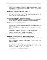
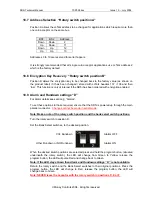
18.7 Address Selection “Rotary switch position A”
Position A allows the ccTalk address to be changed for applications which require more than
one coin acceptor on the same bus.
BS1
BS2
Address
Down
Down
2
Up
Down
11
Down
Up
12
Up
Up
13
Addresses 3 to 10 are reserved for serial hoppers.
It is strongly recommended that all single coin acceptor applications use ccTalk address 2
which is the factory default.
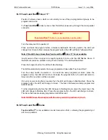
18.8 Encryption Key Recovery “Rotary switch position B”
Position B allows the encryption key to be changed back to the factory value (as shown on
the product label) if it has been changed / stored with ccTalk headers 137 / 136 and then
‘lost’. This function is only of interest if the SR5i has been ordered with encryption enabled
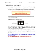
18.9 Alarm and Rundown settings “D”
For Alarm details see section
8
. “Alarms”.
To set these options to those required, ensure that the SR5i is powered up through the main
parallel connector.
Changes cannot be made in serial mode.
Note: Make a note of the rotary switch position and the bank select switch positions.
Turn the rotary switch to position D.
Set the Bank Select switches, to the desired position.
When the desired switch positions are selected press and hold the program button, (situated
underneath the rotary switch), the LED will change from Green to Yellow, release the
program button; the LED will pulse Red and change back to Green.
Note: If the LED stays Green then Alarm and Rundown settings “D” is not available.
Return the rotary switch and the Bank Select switches to their original positions. Press the
program button, the LED will change to Red, release the program button; the LED will
change back to Green.
Note: NEVER leave the acceptor with the rotary switch in positions D, E or F.
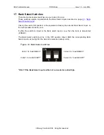
Alarms OFF
CCL Rundown
Alarms ON
Other Rundown or NO Rundown

