7
5. INSTALLATION
Installation of the CC-8946 consists of mounting the Magnetic Lock/Display Panel and the
Armature, and then connecting the attached cable (via a terminal block) to the cable that runs to
the associated Door Control Module.
5.1 Mechanical Installation
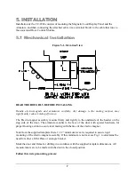
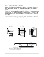
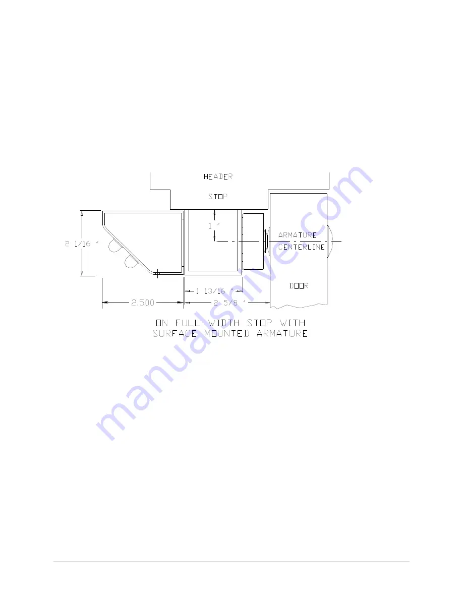
Figure 5-1, Elevation View
READ THOROUGHLY BEFORE INSTALLING
Handle electro-magnets and armatures carefully. Any damage to the mating surfaces may
significantly reduce holding efficiency.
The Electro-magnet assembly mounts firmly and rigidly to the underside of the header on the
stop side of the door. The armature mounts to the face of the door with special hardware for
proper floating action to assure total mating with the face of the electro-magnet.
Note from the supplied template that a 2-1/2” minimum reveal is required to assure rigid
mounting of the electro-magnet assembly. If this minimum is not met see Fig. 1 to determine the
need for either a filler Plate or an angle bracket.
Mark the door and frame for drilling in accordance with the supplied template dimensions. All
measurements are to be made with the door in the closed position.
Follow this 4-step mounting process:

