9
STEP 4 - LOCK & ARMATURE ALIGNMENT
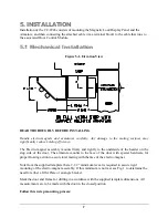
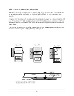
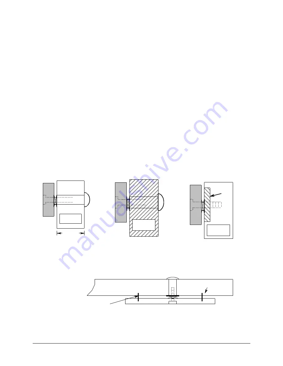
With the electro-magnet energized and the armature fully engaged, position the Lock so that the door
is snug against stops and then tighten the #14 Sheet Metal Screws or the ¼ #20 machine screws
securely.
Using the 3/16” dia. holes in the mounting plate behind the electro-magnet as a physical template, drill
two .159 dia. holes (# 21 drill) and tap the frame for # 10/32 machine screws, or drill two 11/64” dia.
holes in the frame for # 190 sheet metal screws. Secure the mounting plate with the #10 screws and
lock washers.
THE USE OF THESE #10 SCREWS IS IMPORTANT, as they provide resistance to shear rotation
and assure maximum system holding efficiency of the system.
figure 2-A
HOLLOW
METAL
DOOR
1-3/4"
figure 2-B
WOOD
DOOR
figure 2-C
Min. 3/8"
Reinforcing
REINFORCED
DOOR
ROLL PINS
DOOR
ARMATURE
DRIL L 1/4" DIA . 1/2" DEE P
INT O DOOR FOR ROLL P INS
figure 3
TAP 2 ROLL PINS INTO HOLES IN ARMATURE.
MAKING SURE PINS BOTTOM OUT IN HOLES
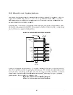
Figure 5-2A
Figure 5-2B
Figure 5-2C
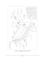
Figure 5-3

