2
Choosing a Location for SMU
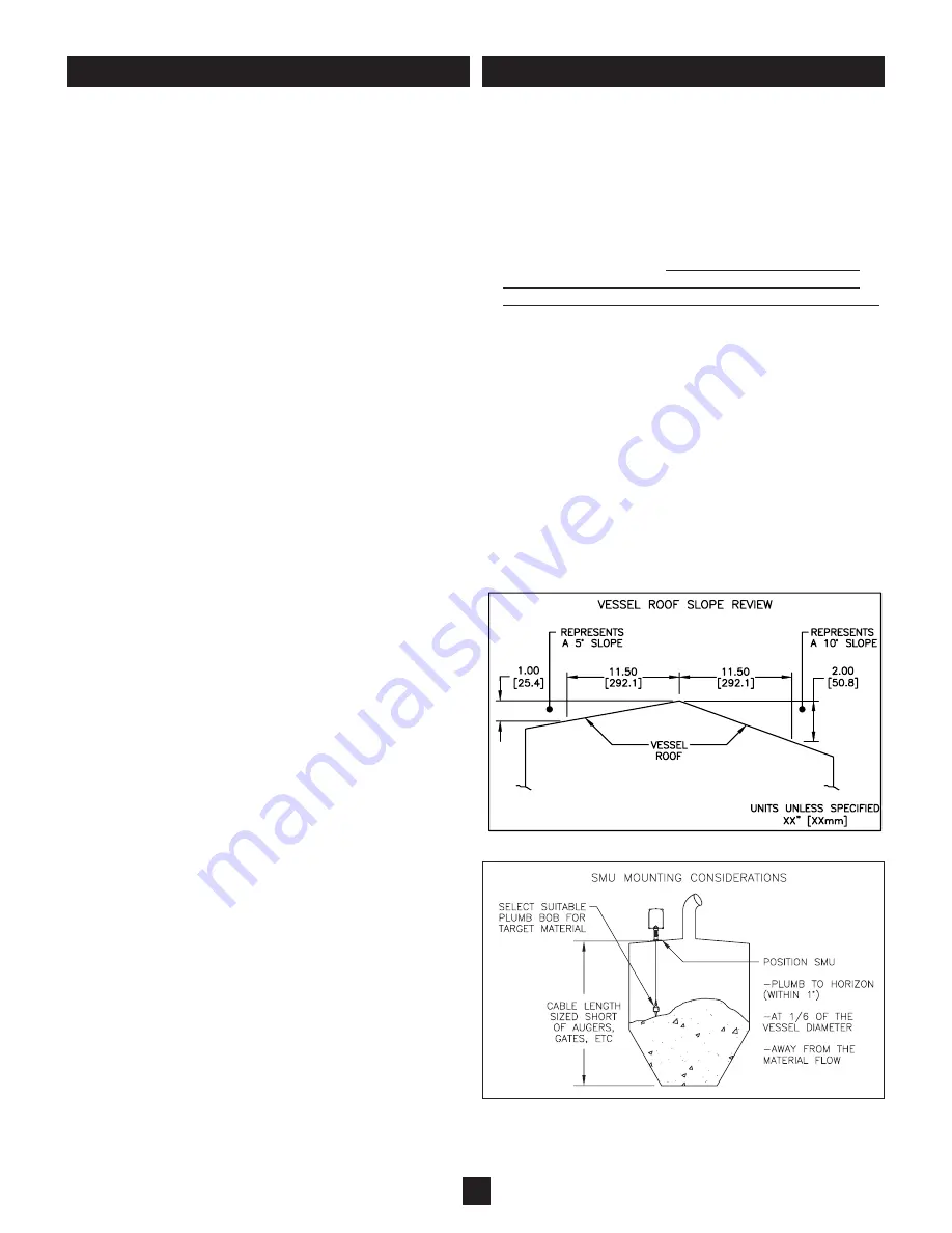
(See Figure 1 and 2)
1) Environment
- SMUs can be configured for ordinary locations
or hazardous locations. The application location must comply
with the SMU classification listed in the specifications. All
SMUs are weatherproof and therefore suitable for outdoor
applications. Note the temperature limits in the specifications.
2) Placement
- Consider the effect that the material's angle of
repose will have on the operation. The SMU will measure the
material height directly below its mounting. For center-fill and
center-discharge vessels, the volumetric average can be
attained by mounting the SMU at a distance equal to 1/6
the vessel diameter away from the outer edge of the vessel
.
Mount the SMU away from internal obstructions and away from
areas where in-flow of material may directly contact the
plumb bob during operation.
Ensure the cable length will not
cause plumb bob extension into augers, slide gates or feed-
ers.
This measurement device cannot factor varying angles
of repose in it’s calculated volumetric displays representing
the material being measured if it is solid as opposed to liquid.
3) Plumb
- The SMU must be mounted plumb (perpendicular to
the ground) within 1 degree. Do not mount the SMU on an
angle. Install an adapter or consider use of a 5 degree or 10
degree flange which can be supplied by Monitor. If the angle
of the roof is unknown, use Figure 1 to approximate. Each 1
inch (25.4 mm) of drop per 11.5 inches (292 mm) of horizon-
tal movement represents approximately five degrees.
PRE-INSTALL ATION CONSIDERATIONS
Figure 1
Figure 2
DIMENSIONS ARE SHOWN IN INCHES WITH MILLIMETER EQUIVALENT IN BRACKETS
Once a measurement cycle is initiated, the
Silo
Patrol
®
SE
SE
sensor (SMU) “smart” motor system controls the descent
of a plumb bob, attached to a heavy-duty stainless steel
cable, into the vessel. The SMU measures the amount of
cable dispensed via its unique optical sensing system.
The SMU’s optic system is completely sealed from the
internal environment of the electronics compartment,
which is isolated and sealed from material ingress in the
mechanical compartment, to ensure long-term reliable
operation.
The descent of the bob is maintained at an optimal speed
by the “smart” motor control system, which contributes to
maximizing the motor life. In conjunction with the unique
dual optical sensing system, the “smart” motor control sys-
tem guarantees that the bob will stop when it contacts the
material surface and eliminates the need for a mechanical
brake. When the bob reaches the material surface, the
SMU reverses the direction of the motor and transmits the
distance value.
In addition, the “smart” motor control system now has an
enhancement feature called Descend-Assist. This feature
would be used if a particular application may be causing
the plumb bob to “cling” to the socket. See Pg. 10 (RS-485)
or Pg. 13 (Analog) of this document to Turn “ON” Descend-Assist
through the ConfigureSensor app in the MISC SETTINGS sec-
tion.
During the ascent of the bob, the SMU measures the
amount of cable gathered and controls the speed of
ascent. This ensures proper cable wrapping in the patent-
ed storage reel and tangle-free operation.
The SMU also includes a Hall effect sensor array that
monitors the movement and position of the swing-arm that
controls the absorption of slack in the cable system during
descent and ascent. The SMU is smarter than ever and
uses this technology to control the cable and plumb bob
travel to ensure reliability of the measurement cycle, even
with harsh changing conditions in the most severe applica-
tions.
The SMU has two output types available that must be
selected at the time of purchase: RS-485 version and
Analog 4-20mA version. The
Silo
Patrol
SE
SE
system, if so
equipped, will also generate auxiliary analog and/or relay
outputs. RS485 communications can be accomplished via
hardwiring or with wireless transceivers.
PRINCIPLE OF OPERATION


