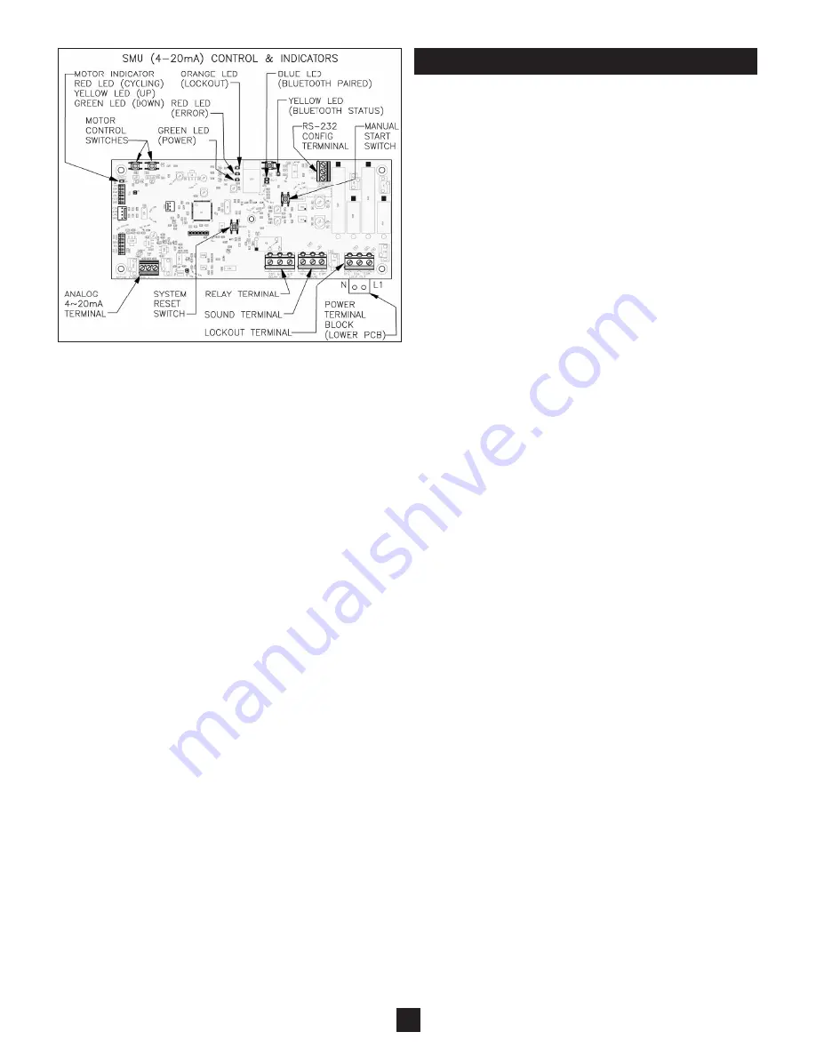
Figure 10
7
SMU Analog(4-20mA) Model
(See Figure 10)
1) Auto Timer -
If desired, the SMU can be configured to self
start at regular time intervals. The auto timer function must be
turned on, and the interval value configured. Then, the
SMU will start a sounding after the passing of the time interval
selected. If auto timer is not desired, then select the auto
timer to be off, and apply a signal to the SOUND terminal to
initiate the measurement process.
2) Values -
The 4~20mA Analog SMU needs to have the 4mA
& 20mA values defined. Configure the distance value down
from the SMU flange that you want to correspond to 4mA &
20mA values. This can be done either way, with 4mA when
vessel is empty and 20mA when vessel is full, or visa versa.
The active signal will over range as much as 3mA and
21.5mA. See Page 8 for the configuration process.
3) Error Reaction -
The 4~20mA analog SMU can be config-
ured to produce an "error" signal on the 4~20mA
signal. Upon an operational error, the SMU will produce a
current value of <2mA or >23mA. The receiving device must
be configured with a respective threshold to recognize the
signal is outside of the standard operational range
(3~21.5mA), and that some form of error has occurred.
4) Signal -
The current signal can be adjusted to update the
signal in two different modes:
CONTINUOUS -
Upon the start of a sounding, the 4~20mA
current value will snap to the value that corresponds to a
vessel full, and then will progress as the bob travels through
its range of motion.
EOT -
Upon the start of a sounding, the 4~20mA current
value will hold a value that corresponds to the previous
distance measurement. When the bob has reached its End
Of Travel, the current output will snap to a value that corre-
sponds to the new reading.
SETUP - CONTINUED


