– 30 –
compressor and the condenser fan should
always operate at the same time. If the
compressor is operating, the temperature
control and defrost control are OK.
115V not present at condenser fan
(Refrigerator Only). If 115V is not present at
the codenser fan, check for an open
temperature control or an open defrost switch.
Note: The compressor and the condenser fan
should always operate at the same time. If the
compressor is operating, the temperature
control and defrost switch are OK.
3. Orange wire open on neutral side of
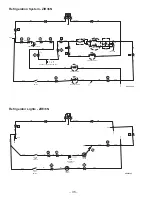
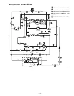
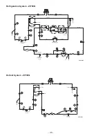
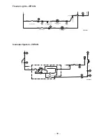
condenser fan. Refer to Schematics and Strip
Circuits.
Evaporator Fan Does Not Operate
Check for the following problems:
1. Evaporator fan faulty. Check for a stuck fan
motor. Check resistance across the fan motor.
Refer to Schematics and Strip Circuits for
resistance values.
2. 115V not present at evaporator fan.
3. Evaporator fan thermostat switch stuck
open (Freezer Only). Refer to Schematics
and Strip Circuits for switch values.
4. Orange wire open on neutral side of
evaporator fan. Refer to Schematics and Strip
Circuits.
Lights (Upper) Do Not Illuminate
Note: If only one light does not illuminate, check
for a faulty lamp or an open yellow or orange wire
in the upper light assembly.
Check for the following problems:
1. Door switch open. Check continuity across
the door switch with the wires disconnected.
2. Light thermostat (switch) open. Refer to
Schematics and Strip Circuits for switch
values.
3. Open wire or faulty connector. Refer to
Schematics and Strip Circuits.
Lights (Lower) Do Not Illuminate
Note: If only one light does not illuminate, check
for a faulty lamp or an open yellow or orange wire
under the evaporator cover.
Check for the following problems:
1. Door switch open. Check continuity across
the door switch with the wires disconnected.
2. Open wire or faulty connector. Refer to
Schematics and Strip Circuits.
Defrost System Check (Freezer)
The automatic defrost function is controlled by the
defrost thermostat switch and the defrost control.
The defrost control contains a motor/cam
mechanism that switches the defrost control
between defrost mode and cooling mode. The
defrost control motor/cam mechanism operates
only when the temperature control (switch) is
closed. After 10 hours of motor/cam mechanism
runtime in cooling mode, the defrost control
switches to defrost mode. The defrost control will
stay in defrost mode, providing 115V to the heater
for 25 minutes of motor/cam mechanism runtime.
The defrost thermostat switch is mounted on the
evaporator, and when closed completes the
neutral side of the defrost heater circuit. The
defrost thermostat switch opens when the
evaporator temperature raises to 45°F and closes
when the evaporator temperature lowers to 25°F.
The defrost thermostat switch typically opens
during the defrost cycle, preventing the heater
from defrosting for the full 25 minutes. The purpose
for the 25-minute defrost mode at the defrost
control is to prevent the compressor from
operating and refreezing any water that may be
dripping from the evaporator.
Check for the following problems:
1. Evaporator heater open. Check resistance
across the evaporator heater. Refer to
Schematics and Strip Circuits for resistance
values.
2. Defrost thermostat switch stuck open.
Refer to Schematics and Strip Circuits for
switch values.
3. Defrost control open in defrost mode.
Manually rotate the defrost control into defrost
mode. Check for continuity across the defrost
control between terminals 2 and 3. Refer to
Schematics and Strip Circuits.
4. Open wire or faulty connector. Refer to
Schematics and Strip Circuits.
Summary of Contents for Monogram ZIFS36N RH
Page 7: ... 5 Specifications ...
Page 8: ... 6 ...
Page 11: ... 9 Notes ...
Page 13: ... 11 GEA00637 Refrigerator Air Flow GEA00860 Freezer Air Flow ...
Page 14: ... 12 Notes ...
Page 30: ... 28 Notes ...
Page 62: ... 60 Notes ...

