background image

Installation Instructions

9

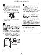
INSTALL THE COOKTOP

A.

Remove the screws on the sides of the cooktop
burner box. Use those screws to attach the side
mounting brackets.

B.

Insert the cooktop centered into the cutout 
opening. Make sure the front edge of the
countertop is parallel to the cooktop. 

Check clearances at the front, back and sides.

Secure the hold-down bracket to the cabinet
sides with screws.

1

Cooktop

INSTALL PRESSURE REGULATOR

WARNING:

Never reuse old flexible

connectors. The use of old flexible connectors can
cause gas leaks and personal injury. Always use
new flexible connectors when installing a gas
appliance.

To reduce the possibility of gas leaks, apply teflon
tape or a thread compound approved for use with
LP or Natural gases to all threaded connections.

A.

Screw the regulator onto the burner box 
bottom pipe connection. Make sure the top of
the regulator is facing toward the cabinet front,
and the arrow on the back of the regulator
points to the cooktop.

B.

Complete the connection between the regulator
and the shut-off valve.

2

Pressure

regulator

Shut-off

valve

Electrical outlet 12

below countertop

To cooktop

Rear view

of

regulator

(note

direction

of arrow)

INSTALL PRESSURE REGULATOR
(cont.)

C.

Before testing for leaks, make sure all burner
knobs are in the OFF position. 

After connecting the cooktop to gas, check 
system for leaks with a manometer. If a manometer
is not available, turn the gas supply on to the
cooktop and use a liquid leak detector at all 
joints and connections to check for leaks. 
Tighten all connections if necessary to prevent gas
leakage in the cooktop or supply line. 

WARNING:

Do not use a flame to 

check for leaks.

Disconnect the cooktop and its individual shut-off
valve 

from the gas supply piping system during any

pressure testing of that system at test pressures
greater than 1/2 psig (3.5 kPa).

Isolate the cooktop

from the gas supply piping

system by closing its individual shut-off valve during
any pressure testing of the gas supply system at
test pressures equal to or less than 1/2 psig (3.5 kPa

).

2

CONNECT ELECTRICAL

• Check to be sure the receptacle is properly

grounded.

• Plug in the power cord.

3

Summary of Contents for ZGU385NSMSS

Page 1: ... see Electrical Connections section of this manual WB28T10185 High Altitude Kit For operation above 5 000 feet order WB28T10185 Conversion Kit This kit includes orifices for both LP and Natural gas operation Installation Preparation 5 INSTALLATION OPTIONS Cooktop and ZVB36 Downdraft Vent Combination Installation These cooktops may be installed with a 36 Monogram Downdraft Vent model ZVB36 See page...

Page 2: ...icular to the sides Observe all minimum clearances 3 Make sure the wall coverings countertop and cabinets around the cooktop can withstand heat up to 200 F generated by the cooktop 3 3 4 36 3 4 21 3 16 deep at center 12 min from cutout to side wall 2 1 2 min from cutout to front of countertop 3 3 8 min from cutout to rear vertical combustibles 12 min from cutout to side wall Installation Preparati...

Page 3: ...the gas supply to the cooktop Install the electrical outlet 12 below the countertop Electrical supply This cooktop features pilotless electric ignition for energy savings and reliability It operates on a 120 volt 60 Hz power supply A separate circuit protected by a 15 amp time delay fuse or circuit breaker is required A properly grounded 3 prong receptacle should be located within reach of the coo...

Page 4: ...p B Complete the connection between the regulator and the shut off valve 2 Pressure regulator Shut off valve Electrical outlet 12 below countertop To cooktop Rear view of regulator note direction of arrow INSTALL PRESSURE REGULATOR cont C Before testing for leaks make sure all burner knobs are in the OFF position After connecting the cooktop to gas check system for leaks with a manometer If a mano...

Page 5: ...st have a deep flat surface to accommodate the cooktop and vent Countertops with a rolled front edge and backsplash will not provide the flat surface area required Review the illustration to determine the countertop surface requirements All cutout clearances for this installation must be observed POWER SUPPLY If local codes permit the vent and cooktop may operate from the same 120V 15 amp duplex o...

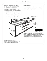
Page 6: ...e with the warming drawer POWER SUPPLY If local codes permit the cooktop and warming drawer may operate from the same 120V duplex outlet Refer to installation instructions for details Install 2x4 or 2x2 anti tip block against rear cabinet wall 9 from cutout floor to bottom of block 23 1 2 min Cooktop 33 7 8 19 1 8 2 1 2 min 1 1 2 cabinet top 5 1 2 min NOTE When installing a Monogram Warming Drawer...

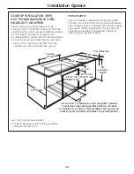
Page 7: ...ered over the oven POWER SUPPLY The oven requires a separate properly grounded 20 Amp 3 wire 208 or 240 volt 60 Hz power supply The cooktop requires a separate 120V power supply See page 8 Where codes permit the gas shut off valve may be located in an adjacent cabinet or other easily accessible location Use two 2x4 s or equivalent runners spaced 25 centerline to centerline in the opening and flush...

Reviews: