background image

12

49-80152   Rev. 8

Installation Instructions

2B

  Alternate Mounting Method 

INSTALL HOOD TO SOFFIT OR 

BENEATH CABINETS

SKIP THIS STEP IF USING WALL MOUNTING 

METHOD

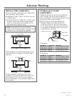
When necessary, the hood may be installed so that it is 

supported by the soffit.

■  The soffit should be constructed with 2 x 4’s.
■  Determine the installation location on the wall.
■  Continue the centerline forward on the bottom of the 

cabinet or soffit.

■  The opening above the hood should allow for the 

10" round duct and clearance to slide the hood back 

against the wall.

■  The 2 x 4 studs must be located as shown in the 

chart, Dim. A. to accept mounting screws. 

■  Drill 1/8" pilot holes into the studs at the locations 

shown in the top view illustration.

IMPORTANT:

 Soffit framing must be capable of 

supporting up to 150 lbs.

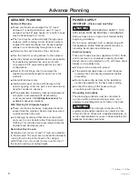
Install Transition Onto Top of Hood
IMPORTANT:

 Remove 

shipping tape from damper 

and check that damper 

moves freely.

■  Place the transition piece 

over the hood exhaust 

and secure with 4 screws 

provided. 

■  Use duct tape to seal the connection. Check to be 

sure the damper moves freely.

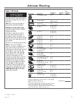
Mount Hood onto Soffit or Cabinet
NOTE:

 If mounting to the underside of a cabinet with a 

recessed bottom, install shims to fill the gap.

■  Drive mounting screws into the studs until they 

protrude 1/4". The 1/4" gap will provide clearance to 

engage the keyhole slots in the top of the hood.

■  Lift hood to installation position. Locate house wiring 

and route through the knockout (from the back or top 

of the hood). 

■  Lift hood onto mounting screws. Slide back against the 

rear wall.

■  Tighten mounting screws.

IMPORTANT:

 For additional support and to 

minimize vibration during operation, the hood must 

be secured to the back wall. Use wall anchors to 

fasten bottom back of hood to the wall.

A

Requires 10-1/2" Min.

Opening For Ductwork

and Hood Installation

A

Duct

Transition

Top of

Hood

“A” Centerline to Stud 

and Keyhole Slots

“B” Hood Width At 

the Top

ZV48T

19-9/16"

40"

ZV48S

23-9/16"

47-15/16"

ZV36T

13-9/16"

28"

ZV36S

17-9/16"

35-15/16"

ZV30T

10-9/16"

22"

ZV30S

14-9/16"

29-15/16"

2"

7-1/2"

A

B

2-9/16"

8"

8-1/8"

6"

Back of Hood

Top View

Front of Hood

1/4" Gap

Push Back

to Wall

Add Shims

If Bottom

Is Recessed

Back

Wall

Cabinet

or

Soffit

Engage Top

Keyhole Slots

1” = 2.5 cm; 1’ = 0.3 m

Summary of Contents for ZV30S

Page 1: ...INSTALLATION INSTRUCTIONS 30 36 and 48 Professional Vent Hoods Monogram com ...

Page 2: ...he service panel and lock the service disconnecting means to prevent the power from being switched on accidentally When the service disconnecting means cannot be locked securely fasten a prominent warning device such as a tag to the service panel CAUTION FOR GENERAL VENTILATING USE ONLY DO NOT USE TO EXHAUST HAZARDOUS MATERIALS EXPLOSIVE MATERIALS OR VAPORS WARNING TO REDUCE THE RISK OF FIRE ELECT...

Page 3: ...l Hood Onto Wall 11 Step 2B Install Hood Beneath Soffit 12 Step 3 Connect Ductwork 13 Step 4 Connect Electrical 13 Step 5 Install Duct Covers 13 Step 6 Install Motor 13 Step 7 Install Filters 14 Step 8 Install Implement Rods 14 PRODUCT DIMENSIONS Model ZV48S With Straight Sides Model ZV36S With Straight Sides Model ZV30S With Straight Sides Model ZV48T With Tapered Sides Model ZV36T With Tapered S...

Page 4: ...t above the countertop OPTIONAL DUCT COVER ACCESSORIES Standard decorative duct covers are available in 6 and 12 heights Duct covers may be stacked in various combinations to conceal the ductwork running from the top of the hood to the ceiling Before you begin you should determine the installation height of the hood and order the correct size duct cover The duct covers should be ordered at the sam...

Page 5: ...n various combinations to reach ceiling heights NOTE Minimum ceiling height for REAR WALL EXHAUST with duct covers is 8 4 when installing at 30 above countertop using 10 elbow Based on 36 countertop height NOTE Additional duct covers may be used to reach higher ceilings Actual Ceiling Height Possible Hood Installation Height 6 Duct Covers 12 Duct Covers 7 11 35 1 8 0 8 0 30 36 1 1 8 1 31 1 8 2 32 ...

Page 6: ...This will also help to accurately locate the ductwork and electrical service Decorative Duct Covers Decorative duct covers 6 and 12 high are available to fit all models The duct cover conceals the ductwork running from the top of the hood to the ceiling or soffit Stack one or more duct covers over the top of the hood to reach your ceiling height POWER SUPPLY IMPORTANT Please read carefully WARNING...

Page 7: ...nces com for available makeup air solutions Duct Piece Dimensions Equivalent Length Quantity Used Total Equivalent Length 10 round to 8 round 5 ft Round straight 1 ft per foot length 3 1 4 x 10 3 1 4 x 12 straight 1 ft per foot length 90 elbow 8 Dia 17 ft 10 Dia 24 ft 45 elbow 8 Dia 10 ft 10 Dia 14 ft 3 1 4 x 12 3 1 4 x 10 90 elbow 15 ft 14 ft 3 1 4 x 10 3 1 4 x 12 45 elbow 8 ft 9 ft 3 1 4 x 10 3 ...

Page 8: ...GING Lift out the wooden crossmember as well as the top protective carton Lift out the four L shaped polystyrene protection profiles Remove the protection moldings around the smaller carton box Remove the small box housing the motor Lift the hood out of the box CAUTION Lift the hood by grasping the outside edges of the inlet opening of the hood Do not lift the hood by the exhaust opening divider d...

Page 9: ... Support with Original Screws 761Dia28 HARDWARE PACKAGE Locate and check contents Screws shown actual size 6 Phillips head screws to secure hood to the wood support 2 secured to wood support 4 Phillips head screws to secure the transition to the hood outlet on the top 2 3 16 hollow wall anchors with screws to secure hood to the wall at the bottom 4 screws to secure the wood support to the wall POZ...

Page 10: ...the wall FOR DUCTING THROUGH REAR WALL Measure 9 7 8 above the marked line for the top of the hood At the centerline mark location for a 10 1 2 diameter hole NOTE Minimum ceiling height for REAR WALL EXHAUST with duct covers is 8 4 when installing at 30 above countertop using 10 elbow House Wiring Location The junction box is fastened to the back of the hood on the right side The recessed back sid...

Page 11: ...ion Check to be sure the damper moves freely Hang Hood On Wood Support Lift the hood and hold close to the installation location Route house wiring through the knockout and into the junction box Place the hood over the wood support Be sure the mounting screws engage the keyhole slots in the back of the hood Tighten the screws WARNING Continue to provide additional support while the hood is mounted...

Page 12: ... connection Check to be sure the damper moves freely Mount Hood onto Soffit or Cabinet NOTE If mounting to the underside of a cabinet with a recessed bottom install shims to fill the gap Drive mounting screws into the studs until they protrude 1 4 The 1 4 gap will provide clearance to engage the keyhole slots in the top of the hood Lift hood to installation position Locate house wiring and route t...

Page 13: ...Rotate motor upwards until it snaps into the spring clip on the right Secure the motor to the hood with the machine screw and lock washer Screw is marked with red or blue paint Plug connector into the motor IMPORTANT Connector ends are designed to mate only one way Match flat and round connectors as shown 4 CONNECT ELECTRICAL Verify that power is turned off at the source WARNING If house wiring is...

Page 14: ...screwdriver to install the stand offs into the bottom of the hood Align the implement rod to the stand offs with the screw hole towards the inside of the hood Secure the rod to the stand offs with the supplied Allen wrench Follow the same procedure on the opposite side FINALIZE INSTALLATION Install the supplied infrared bulb s See the Owner s Manual for instructions to test operation 761Dia26 761D...

Page 15: ...49 80152 Rev 8 15 Notes ...

Page 16: ...goggles should be worn For Monogram local service in your area call 1 800 444 1845 NOTE Product improvement is a continuing endeavor at GE Appliances Therefore materials appearance and specifications are subject to change without notice 49 80151 Rev 9 05 19 GEA Printed in Mexico ...

Page 17: ...INSTRUCTIONS D INSTALLATION Hottes professionnelles de 30 po 36 po et 48 po Monogram com T O U T É L E V E R ...

Page 18: ...ue le courant ne soit accidentellement rétabli S il n est pas possible de bloquer le disjoncteur posez un avertissement bien visible comme une étiquette sur le tableau de distribution ATTENTION POUR UNE UTILISATION DE VENTILATION GÉNÉRALE UNIQUEMENT NE PAS UTILISER POUR ÉVACUER DES MATIÈRES DANGEREUSES DES MATIÈRES EXPLOSIVES OU DES VAPEURS AVERTISSEMENT POUR DIMINUER LES RISQUES D INCENDIE DE DÉC...

Page 19: ...e retombée de plafond 12 Étape 3 Raccorder le conduit 13 Étape 4 Brancher l appareil à l alimentation électrique 13 Étape 5 Installer les cache conduits 13 Étape 6 Installer le moteur 13 Étape 7 Installer les filtres 14 Étape 8 Installer les tiges d ustensiles 14 DIMENSIONS DU PRODUIT Modèle ZV48S avec côtés droits Modèle ZV36S avec côtés droits Modèle ZV30S avec côtés droits Modèle ZV48T avec côt...

Page 20: ...tion spécifiques au dessus du comptoir CACHE CONDUITS EN OPTION Les cache conduits décoratifs standard sont disponibles en hauteurs de 6 po et 12 po Les cache conduits peuvent être superposés dans diverses combinaisons pour dissimuler les conduits du haut de la hotte jusqu au plafond Avant de commencer vous devez déterminer la hauteur d installation de la hotte et commander le cache conduit de la ...

Page 21: ... 4 po dans une installation à 30 po au dessus du comptoir avec un coude de 10 po Basée sur une hauteur de comptoir de 36 po REMARQUE Des cache conduits supplémentaires peuvent être utilisés pour atteindre des plafonds plus hauts Hauteur réelle du plafond Hauteur d installation possible de la hotte Cache conduits de 6 po Cache conduits de 12 po 7 pi 11 po 35 po 1 8 pi 0 po 8 pi 0 po 30 po 36 po 1 1...

Page 22: ...inition du mur Ainsi vous pourrez précisément repérer l emplacement du conduit et du système électrique Cache conduits décoratifs Des cache conduits décoratifs de 6 po et 12 po de hauteur sont disponibles pour s adapter à tous les modèles La garniture dissimule le conduit d évacuation du haut de la hotte jusqu au plafond ou jusqu à la retombée de plafond Superposez un ou plusieurs cache conduits s...

Page 23: ... 8 po 5 pi Rond droit 1 pi par pied de longueur Droit de 3 1 4 po x 10 po 3 1 4 po x 12 po 1 pi par pied de longueur Coude de 90 8 po de diam 17 pi 10 po de diam 24 pi Coude de 45 8 po de diam 10 pi 10 po de diam 14 pi Coude de 90 3 1 4 po x 12 po 3 1 4 po x 10 po 15 pi 14 pi Coude de 45 3 1 4 po x 10 po 3 1 4 po x 12 po 8 pi 9 pi Coude plat de 90 3 1 4 po x 10 po 3 1 4 po x 12 po 33 pi 36 pi Cond...

Page 24: ...on supérieur Retirez les quatre protecteurs en L en polystyrène Retirez les moulures de protection autour de la plus petite boîte en carton Retirez la petite boîte contenant le moteur Sortez la hotte de la boîte ATTENTION Soulevez la hotte en saisissant les rebords extérieurs de l ouverture de son entrée d air Ne soulevez pas la hotte par le séparateur de l ouverture de ventilation cela risquerait...

Page 25: ...vis d origine 761Dia28 TROUSSE DE QUINCAILLERIE Localisez et vérifiez le contenu de l emballage Vis illustrées en taille réelle 6 vis à tête Phillips pour fixer la hotte au support en bois 2 vis fixées au support en bois 4 vis à tête Phillips pour fixer le conduit de transition vers la sortie sur le dessus de la hotte 2 ancrages muraux creux 3 16 po avec vis pour fixer au mur la partie inférieure ...

Page 26: ...trale marquez l emplacement d un trou de 10 1 2 po de diamètre REMARQUE La hauteur minimale du plafond pour une ÉVACUATION PAR LE MUR ARRIÈRE avec cache conduits est de 8 pi 4 po dans une installation à 30 po au dessus du comptoir avec un coude de 10 po Emplacement du câblage La boîte de jonction est fixée à droite sur la partie arrière de la hotte Le côté arrière en retrait de la hotte offre une ...

Page 27: ...librement Accrocher la hotte sur le support en bois Soulevez la hotte et maintenez la près de l emplacement d installation Acheminez le câblage de la maison à travers l alvéole défonçable jusque dans la boîte de jonction Placez la hotte sur le support en bois Assurez vous que les vis de montage s engagent dans les encoches en trou de serrure à l arrière de la hotte Serrez les vis AVERTISSEMENT Fou...

Page 28: ...RQUE Si la hotte est fixée à une armoire pourvue d une base en retrait installez des cales pour combler l espace Installez les vis dans les montants en les laissant dépasser de 1 4 po Cette saillie de 1 4 po permet d engager les vis dans les encoches en trou de serrure de la partie supérieure de la hotte Soulevez la hotte en position d installation Localisez le câblage de la maison et acheminez le...

Page 29: ...eur à la hotte avec la vis à métaux et la rondelle de blocage La vis est marquée de peinture rouge ou bleue Branchez le connecteur dans le moteur IMPORTANT Les extrémités du connecteur sont conçues pour ne se brancher que dans un seul sens Faites correspondre les connecteurs plats et ronds comme indiqué 4 BRANCHER L APPAREIL À L ALIMENTATION ÉLECTRIQUE Vérifiez que l alimentation est coupée à la s...

Page 30: ...nevis à lame plate pour installer les entretoises au bas de la hotte Alignez la tige d ustensiles sur les entretoises avec le trou de vis vers l intérieur de la hotte Fixez la tige aux entretoises avec la clé Allen fournie Suivez la même procédure du côté opposé FINALISER L INSTALLATION Installez la ou les ampoules infrarouges fournies Reportez vous au Manuel de l utilisateur pour les instructions...

Page 31: ...49 80152 Rév 8 15 Notes ...

Page 32: ... joindre le service à la clientèle de MonogramMD dans votre région appelez le 1 800 444 1845 REMARQUE L amélioration des produits est une préoccupation constante chez Électroménagers GE Par conséquent les matériaux l apparence et les spécifications peuvent être modifiés sans préavis 49 80151 Rév 9 05 19 GEA Imprimé au Mexique ...

Reviews: