49-80329 Rev. 5
3
Design Information
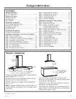
CONTENTS
Design Information
Product Dimensions
...................................................... 3
Advance Planning
Advance Planning
........................................................ 4
Power Supply
............................................................... 4
Duct Fittings
................................................................ 5
Installation Preparation
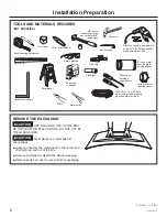
Tools and Materials Required ....................................... 6
Remove the Packaging
................................................ 6
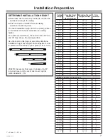
Installation Height .........................................................
7
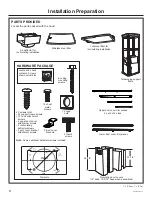
Parts Provided
.............................................................. 8
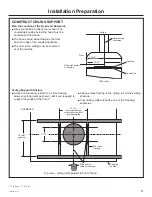
Installation Preparation
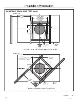
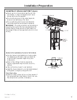
Construct Ceiling Support .............................................
9
Installation Instructions—Vented to the Outside
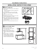
Step 1, Mount Template
.............................................. 12
Step 2, Adjust Frame Height
....................................... 12
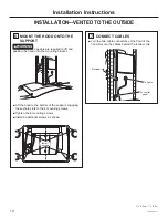
Step 3, Cut Duct to Length for Vented Installation
...... 13
Step 4, Install the Support Frame
............................... 13
Step 5, Install Hood Attachment Screws
..................... 13
Step 6, Mount the Hood onto the Support
.................. 14
Step 7, Connect Cables
.............................................. 14
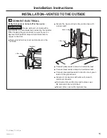
Step 8, Connect Electrical
........................................... 15
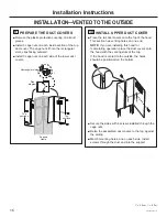
Step 9, Prepare the Duct Covers
................................ 16
Step 10, Install Upper Duct Cover
.............................. 16
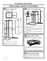
Step 11, Install Lower Duct Cover
..............................
17
Step 12, Install Duct Cover Trim
.................................
17
Step 13, Install Metal Filter
..........................................
17
Step 14, Finalize Installation
.......................................
17
Installation Instructions—Recirculating
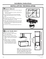
Step 1, Mount Template
.............................................. 18
Step 2, Adjust Frame Height
....................................... 18
Step 3, Install Air Deflector, Cut Duct
for Recirculating Operation .............................
19
Step 4, Install Upper Support Frame
..........................
19
Step 5, Install Lower Structure to Upper Structure
.....
20
Step 6, Install Blower/Motor
........................................
20
Step 7, Install Hood Attachment Screws
.....................
20
Step 8, Mount the Hood onto the Support
..................
20
Step 9, Connect Cables
.............................................. 21
Step 10, Connect Electrical
......................................... 21
Step 11, Prepare the Duct Covers
.............................. 22
Step 12, Install Upper Duct Cover
.............................. 22
Step 13, Install Lower Duct Cover
.............................. 22
Step 14, Install Duct Cover Trim
................................. 23
Step 15, Install Filters
.................................................. 23
Step 16, Finalize Installation
....................................... 23
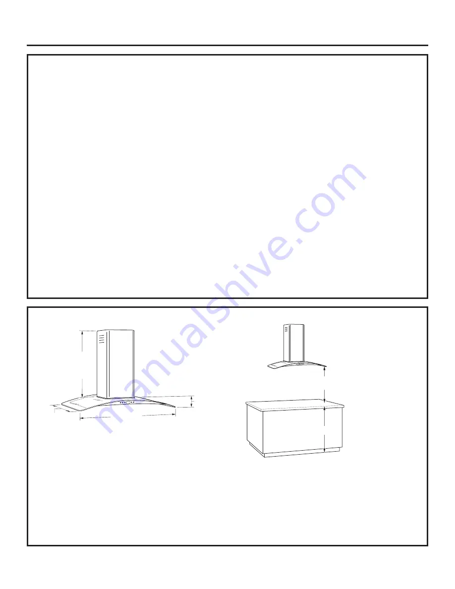
PRODUCT DIMENSIONS
These vent hoods are supplied with a support frame for
ceiling heights of 7’-11” to 10’-1”.
Decorative duct covers conceal the ductwork running
from the top of the hood to the ceiling.
ZX92510 accessory is available for ceiling heights of
9’-1” to 10’-1”.
NOTE:
Installation height should be measured from the
cooking surface to the bottom of the outer glass portion
of the hood.
This hood must be installed 24” min. and 30” max.
above the cooking surface. The cooking surface should
be at least 36” above the floor.
This hood may be vented to the outdoors, or it can be
installed for recirculating operation.
This hood can be installed over any Monogram electric
or gas cooktop. It cannot be installed over a Monogram
Professional cooktop or range.
* The supplied duct cover fits 7’-11” to 9’ ceiling heights.
For 9’-1” to 10’-1” ceilings, order ZX92510.
27 9/16"
3 1/4"
35 7/8"
*Height
to
Ceiling
2 3/4"
*Height to
ceiling
27 9/16"
35 7/8"
24" min.*
30" max.*
36" min.
* Exact installation
height depends on
ceiling height.
1” = 2.5 cm; 1’ = 0.3 m


