background image

31-2000730   Rev. 0

5

Installation Instructions

STEP 1


DETERMINE HOOD AND DUCTWORK LOCATIONS

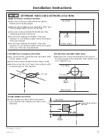
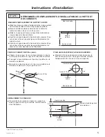
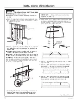
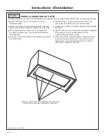
MARK LOCATION OF WOOD SUPPORT

■  Use a level to draw a cooktop centerline location. 

Draw the line to ceiling height.

■  Measure desired distance from the bottom of the hood 

to the cooking surface, 30” min. to 36” max.

■  Use a level to draw a straight horizontal pencil line 

indicating the bottom of the hood.

■  From the line indicating the bottom of the hood, 

measure 16” up and draw another line for the location 

of the wood support.

■  From the line indicating the bottom of the hood, 

measure 28” up and draw another line for the location 

of the top of the hood. See illustration.

16”

Bottom of Hood

Wood 

Support

Top of Hood

28”

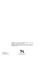
FOR VERTICAL (Straight Up) DUCTING:

■  Use a level to draw a centerline from the bottom of the 

hood to ceiling or soffit. 

■  Extend the centerline forward on the ceiling or soffit.
■  Mark the center of a 8-1/2” hole on the ceiling or soffit 

by measuring 8-1/2” from the wall.

FOR DUCTING THROUGH REAR WALL:

■  Measure 4-3/4” above the marked line for the top of 

the wood support. At the centerline, mark location for a 

8-1/2” diameter hole.

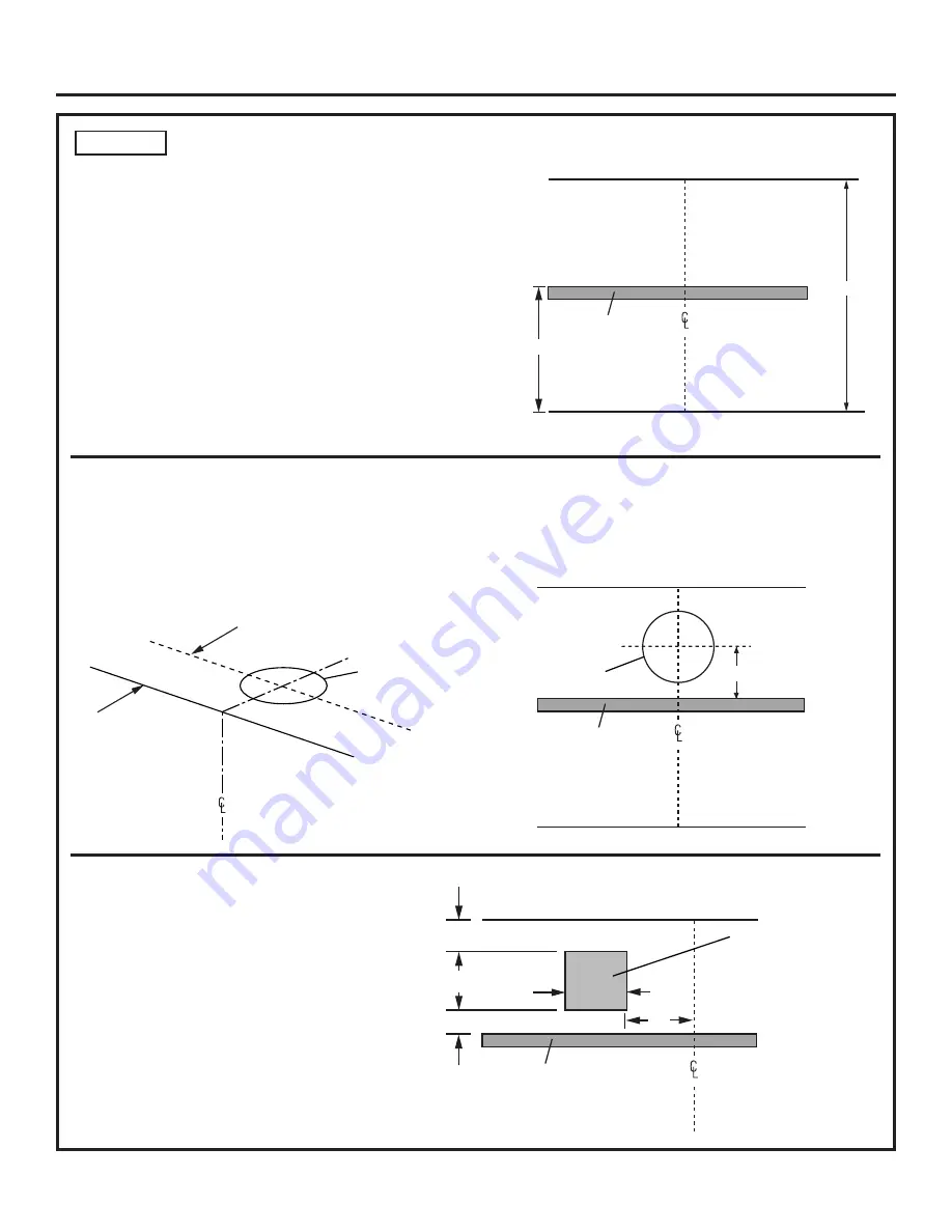
HOUSE WIRING LOCATION:

■  Locate junction box above the wood support 

and to the left of the centerline as shown in the 

illustration.

8-1/2” hole

8-1/2”

Bottom of Hood

Wood 

Support

Top of Hood

4-3/4”

8-1/2” hole

Bottom of Hood

Wood 

Support

Top of Hood

Locate House Junction 

Box Here

2”

2-3/4”

7”

6”

6”

1” = 2.5 cm; 1’ = 0.3 m

Summary of Contents for ZVC48DNB1

Page 1: ...INSTALLATION INSTRUCTIONS 48 Designer Brass Hood ZVC48DNB1 MONOGRAM COM ...

Page 2: ...iance is properly grounded For Monogram local service in your area 800 444 1845 For Monogram Service in Canada call 800 561 3344 For Monogram Parts and Accessories call 800 626 2002 If you received a damaged vent hood you should contact your dealer CAUTION Due to the weight and size of these vent hoods and to reduce the risk of personal injury or damage to the product TWO PEOPLE ARE REQUIRED FOR P...

Page 3: ...LS AND MATERIALS REQUIRED Not supplied 28 16 22 SIDE VIEW FRONT VIEW 38 5 8 48 Phillips screwdriver Flashlight Safety glasses Electric or battery operated drill 1 8 drill bit 3 16 drill bit Phillips driver Pencil Level Step ladder Tape measure Safety Gloves Wood Support with short Phillips head screws 2 long Square Drive flat head screws to secure the wood support to the wall Square drive bit 2 sh...

Page 4: ... this instruction as well as the hood insert installation instructions Wall Framing for Adequate Support This hood is heavy Adequate structural support must be provided Hood must be secured to vertical studs in the wall It is strongly recommended that the hood and hood insert be on site before final framing and wall finishing This will also help to accurately locate the ductwork and electrical ser...

Page 5: ... of the top of the hood See illustration 16 Bottom of Hood Wood Support Top of Hood 28 FOR VERTICAL Straight Up DUCTING Use a level to draw a centerline from the bottom of the hood to ceiling or soffit Extend the centerline forward on the ceiling or soffit Mark the center of a 8 1 2 hole on the ceiling or soffit by measuring 8 1 2 from the wall FOR DUCTING THROUGH REAR WALL Measure 4 3 4 above the...

Page 6: ...til they protrude 1 4 forward This 1 4 gap will provide clearance to hang the hood IMPORTANT Framing must be capable of supporting up to 150 lbs Place the hood over the wood support Be sure the mounting screws engage the keyhole slots in the back of the hood Tighten the screws Confirm hood position is correct Install additional 2 short screws to secure the hood to the wood support Install 2 medium...

Page 7: ...mensions are different You may remote mount the control for the Hood Insert if desired Skip Step 1 Insert Hood Liner You may discard the Liner it is not required Start at Step 2 Connect Electrical Be sure to follow the remainder of the Custom Hood Insert installation instructions to properly fasten the Insert to the Hood Pay special attention to the step that says to push the Insert firmly up prio...

Page 8: ...ates NOTE While performing installations described in this book safety glasses or goggles should be worn NOTE Product improvement is a continuing endeavor at Monogram Therefore materials appearance and specifications are subject to change without notice ...

Page 9: ...INSTRUCTIONS D INSTALLATION Hotte en laiton stylisée de 48 po ZVC48DNB1 MONOGRAM COM ...

Page 10: ... Monogram au Canada appelez le 800 561 3344 Pour les pièces et accessoires Monogram appelez le 800 626 2002 Si vous avez reçu une hotte endommagée contactez immédiatement votre détaillant ATTENTION Compte tenu du poids et de la dimension de ces hottes et afin de réduire les risques de blessure et pour ne pas endommager le produit LEUR INSTALLATION DOIT ÊTRE EFFECTUÉE PAR DEUX PERSONNES AVERTISSEME...

Page 11: ...MATÉRIEL NÉCESSAIRES Non fournis 28 po 16 po 22 po VUE LATÉRALE VUE AVANT 38 5 8 po 48 po Tournevis Phillips Lampe torche Lunettes de sécurité Perceuse électrique ou à batterie Foret de 1 8 po Foret de 3 16 po Tournevis Phillips Crayon Niveau Escabeau Ruban à mesurer Gants de sécurité Support en bois avec vis courtes à tête Phillips 2 vis longues plates à carré conducteur pour fixer le support en ...

Page 12: ... installation pour la garniture de hotte Charpente murale pour un support adéquat Cette hotte est très lourde Pour soutenir la hotte la charpente murale doit être adéquate La hotte doit être fixée aux montants verticaux du mur Il est fortement recommandé que la hotte et la garniture de hotte soient sur le site d installation avant la mise en place finale et la finition du mur Ainsi vous pourrez pr...

Page 13: ...lustration 16 po Bas de la hotte Support en bois Haut de la hotte 28 po POUR UN CONDUIT VERTICAL droit Utilisez un niveau pour tracer une ligne médiane du bas de la hotte jusqu au plafond ou jusqu à la retombée du plafond Prolongez la ligne médiane vers l avant sur le plafond ou la retombée du plafond Marquez le centre d un trou de 8 1 2 po sur le plafond ou la retombée du plafond 8 1 2 po à parti...

Page 14: ...lie de 1 4 po permettra de suspendre la hotte IMPORTANT La charpente doit pouvoir soutenir une charge de 150 lb 68 kg Placez la hotte sur le support en bois Assurez vous que les vis de montage s engagent dans les encoches en trou de serrure à l arrière de la hotte Serrez les vis Assurez vous que la position de la hotte est la bonne Installez 2 vis courtes supplémentaires pour fixer la hotte au sup...

Page 15: ...onter à distance la commande pour la hotte si vous le désirez Omettez l étape 1 Insérer la doublure de hotte Vous pouvez jeter la doublure elle n est pas nécessaire Commencez à l étape 2 Brancher l appareil à l alimentation électrique Assurez vous de suivre le reste des instructions d installation de la garniture de hotte personnalisée pour fixer correctement la garniture à la hotte Prêtez une att...

Page 16: ...procédure d installation décrite dans ce manuel il est recommandé de porter des lunettes de sécurité REMARQUE L amélioration des produits est un effort continu chez Monogram Par conséquent les matériaux l apparence et les spécifications peuvent être modifiés sans préavis ...

Reviews: