background image

12

31-2000734   Rev. 4

Installation

4   (Alternate Mounting Method) 

INSTALL HOOD TO SOFFIT

SKIP THIS STEP IF USING WALL MOUNTING 
METHOD

IMPORTANT

: Soffit framing must be capable of 

supporting 100 lbs for 36” models and 150 lbs for 
48”models.

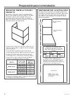
When necessary the hood may be installed so that it 
is supported by the soffit.

•  The soffit should be constructed with 2”x4”s.

•  Use a level to draw the cooktop or range center line.

•  Continue the centerline forward on the bottom of the 

soffit.

•  Install horizontal wood supports between the 2”x4”, 

at distance A to the left and right, as per the table 
below.

B

A

A

“A” 
Centerline 
to Center 
Stud

“B” 
Opening for 
Ductwork for 
top venting

“C” 
Opening for 
Ductwork for 
back venting

36” Models

11-3/8”

10-5/8”H x 
11-1/4”W

10-1/2” H x 
13-1/4” W

48” Models

17-3/8”

C

3

  INSTALL HOOD ONTO WALL

•  Pull house wiring through knockout at the back or 

top of the hood.

•  Lift the hood and place over the hooks on the 

installation bar. Allow the hood to slide down into 
position.

•  Check to be sure the hood is level and centered.

•  Tighten wall anchor screws (C) to finish hood body 

installation to the wall.

•  Remove cover from junction box inside the hood.

Centerline of 
Installation Space

24” minimum over electric 

range or cooktop, or 30” 

minimum over gas range 

or cooktop, and 36” 

recommended maximum.

Summary of Contents for ZVW1360

Page 1: ...LATION INSTRUCTIONS 36 and 48 Wall Hood ZVW1360 ZVW1480 With QuietBoost Blower MONOGRAM COM Para consultar una version en español de este manual de instrucciones visite nuestro sitio de internet monogram com ...

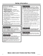
Page 2: ...ue to the weight and size of these vent hoods and to reduce the risk of personal injury or damage to the product TWO PEOPLE ARE REQUIRED FOR PROPER INSTALLATION WARNING Disconnect all electrical power at the main circuit breaker or fuse box before installing WARNING TO REDUCE THE RISK OF FIRE ELECTRIC SHOCK OR INJURY TO PERSONS OBSERVE THE FOLLOWING A Installation work and electrical wiring must b...

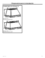
Page 3: ...31 2000734 Rev 4 3 Installation Preparation PRODUCT DIMENSIONS 36 Models Requires a 36 opening 48 Models Requires a 48 opening 18 15 23 5 8 22 36 18 22 48 15 35 5 8 ...

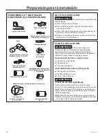
Page 4: ... INSTALLATION Ŷ 1 Hardware Package Ŷ 1 Literature Package Ŷ 1 Installation Template PARTS NEEDED FOR INSTALLATION Ŷ 1 Strain Relief Ŷ 1 Wall or Roof Cap Ŷ All Metal Ductwork WARNING PERSONAL INJURY HAZARD Because of the weight and size of the rangehood canopy It is recommended that 2 people are used to install the range hood Failure to properly lift rangehood could result in damage to the product ...

Page 5: ...48 model Hood Body Metal Installation Bracket 3 Baffle Filters 4 with 48 models QTY 2 3 16 dry wall anchors with screws Used for hood bottom mounting screw holes Use 5 16 drill for pilot hole QTY 4 or 8 M4 screws Used to mount motor QTY 4 8 x 1 3 4 AB screw Used to mount the installation bar Use 1 8 drill for pilot hole QTY 4 2 9mm x 6mm PZ screws Used to attach the damper A B C D ...

Page 6: ... to the wall The lower duct cover alone can be used and must be secured with the duct cover bracket See table below for duct cover kit part numbers based on model See the next page for duct cover installation height information X Distance from hood to cooktop Varies depending on the installation Required 24 minimum over electric range or 30 minimum over gas range The recommended maximum is 36 Requ...

Page 7: ...24 28 7 5 27 29 8 8 24 29 9 9 24 29 7 6 28 30 8 9 24 30 9 10 24 30 7 7 29 31 8 10 24 31 9 11 24 31 7 8 30 30 32 8 11 30 24 32 10 0 30 24 32 7 9 30 31 31 33 9 0 30 31 24 33 10 1 30 31 24 33 7 10 30 32 32 34 9 1 30 32 24 34 10 2 30 32 24 34 7 11 31 33 33 35 9 2 30 33 24 35 10 3 30 33 24 35 8 0 32 34 34 36 9 3 30 34 24 36 10 4 30 34 24 36 8 1 33 35 35 36 9 4 30 35 10 5 30 35 8 2 34 36 36 9 5 30 36 10...

Page 8: ...Please read carefully WARNING FOR PERSONAL SAFETY THIS APPLIANCE MUST BE PROPERLY GROUNDED Remove house fuse or open circuit breaker before beginning installation Do not use an extension cord or adapter plug with this appliance Follow National Electrical Codes or prevailing local codes and ordinances Electrical supply These vent hoods must be supplied with 120V 60Hz and connected to a properly gro...

Page 9: ...in the installation space FOR BACK VENTING Ŷ RU GXFWHG LQVWDOODWLRQ WKURXJK WKH EDFN WKH x13 1 4 W cut out for the duct in the wall must be centered in the installation space left to right and located 5 7 8 above intended install height from bottom of the hood Installation Preparation 6 1 4 5 7 8 10 1 2 H x13 1 4 W Bottom of Hood Ŷ 7KH KRRG MXQFWLRQ ER NQRFNRXW LV ORFDWHG WR WKH left from center o...

Page 10: ...ting Through Rear Wall NOTE Check to make sure back damper will not interfere with studs electrical or plumbing before making cut out Back damper accessory UXBDA812 must be purchased separately for venting through the rear wall Measure 5 7 8 up along the centerline from the horizontal line indicating bottom of the hood Make an 10 1 2 x13 1 4 cut out centered left to right along the centerline Hous...

Page 11: ... back damper accessory UXBDA812 must be purchased separately Remove the square knockout panel on hood body for back venting Install the back damper to the hood body as shown in Figure B using screws provided with the accessory Uninstall the motor mounting plate from top venting position Save the screws Install the metal plate provided with the accessory to cover the opening for top damper Remove t...

Page 12: ...the left and right as per the table below B A A A Centerline to Center Stud B Opening for Ductwork for top venting C Opening for Ductwork for back venting 36 Models 11 3 8 10 5 8 H x 11 1 4 W 10 1 2 H x 13 1 4 W 48 Models 17 3 8 C 3 INSTALL HOOD ONTO WALL Pull house wiring through knockout at the back or top of the hood Lift the hood and place over the hooks on the installation bar Allow the hood ...

Page 13: ...tallation to the back wall Follow instructions on page 10 House Wiring Locations for wiring setup Lift hood onto mounting screws Slide back against the rear wall Pull house wiring through the knockout at the rear or top of the hood Tighten mounting screws E Once the hood is secured to the soffit drive screws C to secure the hood to the back wall 1 4 Gap Soffit Back Wall Engage Keyhole Slots and Pu...

Page 14: ...clockwise around the green grounding screw and above the bracket Firmly tighten the screw over the loop Replace junction box cover and ensure wires are not pinched NOTE For corded installation Use only with rangehood cord connection kits that have been investigated and found acceptable for use with this model rangehood 7 CONNECT DUCTWORK Connect the house ducting to the top damper as shown in Figu...

Page 15: ...e it from the hood 4 Uninstall the control box cover 5 For a maximum of 390 CFM Unit can operate with 4 speeds Low Medium High Boost i Disconnect connectors of the BROWN wire ii Remove the cap attached to the connector of the RED wire iii Connect the mating connector of the BROWN wire and the RED wire iv Attach the cap to the open BROWN wire connector 6 Reinstall control box cover and secure contr...

Page 16: ...OTE While performing installations described in this book safety glasses or goggles should be worn NOTE Product improvement is a continuing endeavor at Monogram Therefore materials appearance and specifications are subject to change without notice ...

Page 17: ...INSTRUCCIONES DE INSTALACIÓN Campana de Pared de 36 y 48 ZVW1360 ZVW1480 Con Extractor QuietBoost MONOGRAM COM ESPAÑOL ...

Page 18: ...TAR CON DOS PERSONAS PARA UNA INSTALACIÓN ADECUADA ADVERTENCIA Desconecte toda la corriente eléctrica del disyuntor principal o de la caja de fusibles antes de la instalación ADVERTENCIA PARA REDUCIR EL RIESGO DE INCENDIO DESCARGA ELÉCTRICA O LESIONES A PERSONAS CUMPLA CON LOS SIGUIENTES PUNTOS A El trabajo de instalación y el cableado eléctrico deben ser realizados por una persona s calificada de...

Page 19: ...31 2000734 Rev 4 3 Preparación para la instalación DIMENSIONES DEL PRODUCTO Modelos de 36 Requiere una abertura de 36 Modelos de 48 Requiere una abertura de 48 18 15 23 5 8 22 36 18 22 48 15 35 5 8 ...

Page 20: ...es PIEZAS PROVISTAS PARA LA INSTALACIÓN Ŷ 1 Paquete de Herramientas Ŷ 1 Paquete Escrito Ŷ 1 Plantilla de Instalación PIEZAS NECESARIAS PARA LA INSTALACIÓN Ŷ 1 Amortiguador de Refuerzo Ŷ Una Tapa de Pared o Techo Ŷ Toda la Tubería Metálica ADVERTENCIA RIESGO DE LESIONES PERSONALES Debido al peso y tamaño de la base de la campana extractora Es recomendable que la campana extractora sea instalada por...

Page 21: ...os de 48 PAQUETE DE MATERIALES Ubique y controle los contenidos Cant 4 u 8 Tornillos M4 Usados para montar el motor Cant 4 Tornillos 8 x 1 3 4 de AB Usados para montar la barra de instalació Use una broca de 1 8 para el agujero piloto Cant 4 Tornillos PZ de 2 9mm x 6mm Usados para adherir el regulador A B C D Cant 2 Anclajes para pared de yeso de 3 16 con tornillos Usados para los agujeros de los ...

Page 22: ...altura de instalación de la tapa del conducto DIMENSIONES DE LA INSTALACIÓN Las tapas de los conductos de las campanas pueden ser ajustadas en diferentes alturas de cielorrasos dependiendo de la distancia entre la parte inferior de la campana y la superficie de cocción distancia X Consulte la Tabla de Alturas de Instalación X Distancia desde la campana hasta la superficie de cocción Varía dependie...

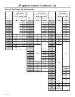
Page 23: ...5 27 8 6 24 27 9 7 24 27 7 4 26 28 8 7 24 28 9 8 24 28 7 5 27 29 8 8 24 29 9 9 24 29 7 6 28 30 8 9 24 30 9 10 24 30 7 7 29 31 8 10 24 31 9 11 24 31 7 8 30 30 32 8 11 30 24 32 10 0 30 24 32 7 9 30 31 31 33 9 0 30 31 24 33 10 1 30 31 24 33 7 10 30 32 32 34 9 1 30 32 24 34 10 2 30 32 24 34 7 11 31 33 33 35 9 2 30 33 24 35 10 3 30 33 24 35 8 0 32 34 34 36 9 3 30 34 24 36 10 4 30 34 24 36 8 1 33 35 35 ...

Page 24: ...a bien leer cuidadosamente ADVERTENCIA PARA SEGURIDAD PERSONAL ESTE APARATO DEBE CONECTARSE A TIERRA DE MANERA ADECUADA Quite el fusible o abra el interruptor de circuitos antes de comenzar la instalación No utilice un cable de extensión o un enchufe adaptador con este artefacto Siga los Códigos Eléctricos Nacionales o códigos y ordenanzas locales vigentes Suministro eléctrico Estas campanas de ve...

Page 25: ...espacio de instalación PARA LA VENTILACIÓN TRASERA Ŷ 3DUD XQD LQVWDODFLyQ FRQ FRQGXFWR D WUDYpV GH OD SDUWH trasera el espacio libre de 10 H x 13 W desde el conducto de la pared deberá estar centrado en el espacio de instalación de izquierda a derecha ubicado 5 7 8 sobre la altura de instalación esperada desde la parte inferior de la campana 6 1 4 5 7 8 Parte Inferior de la Campana Ŷ O WDEOHUR GH ...

Page 26: ...24 sobre una cocina eléctrica o un mínimo de 30 sobre una cocina a gas y un máximo recomendado de 36 Use un nivel para dibujar la ubicación de la línea central de la superficie de cocción Mida 16 desde la línea horizontal que indica la parte inferior de la campana Dibuje otra línea horizontal para indicar la parte inferior de la barra de instalación Use un nivel para dibujar la ubicación de la lín...

Page 27: ... de la pared se deberá adquirir el accesorio del regulador UXBDA812 de forma separada Retire el panel cuadrado preperforado del cuerpo de la campana para la ventilación trasera Instale el regulador trasero al cuerpo de la campana como se muestra en la Figura B usando los tornillos provistos con el accesorio Desinstale la placa de montaje del motor de la posición de ventilación superior Guarde los ...

Page 28: ...ínea Central hasta la Viga Central B Abertura para el conducto de la ventilación superior C Abertura para el conducto de la ventilación trasera 36 Modelos 11 3 8 10 5 8 H x 11 1 4 W 10 1 2 H x 13 1 4 W 48 Modelos 17 3 8 B A A C 3 INSTALACIÓN DE LA CAMPANA EN LA PARED Pase el cableado hogareño a través del tablero sobre la parte trasera o superior de la campana Levante la campana y coloque la misma...

Page 29: ...leado Hogareño para la configuración del cableado Levante la campana sobre los tornillos de montaje Vuelva a deslizar la misma sobre la pared trasera Pase el cableado hogareño a través del tablero sobre la parte trasera o superior de la campana Ajuste los tornillos de montaje Una vez que la campana se encuentre asegurada al sofito coloque los tornillos C para asegurar la campana a la pared trasera...

Page 30: ...rde y sobre el soporte De manera firme ajuste el tornillo sobre el rollo Reemplace la tapa de la caja de empalmes y asegúrese de que los cables no hayan sufrido pellizcos NOTA Para una instalación con cables use la misma sólo con los kits de conexión de cables para campanas de cocina que fueron investigados y que se encontró que su uso es aceptable con este modelo de campana para cocina ADVERTENCI...

Page 31: ...ducir lesiones personales o daños sobre el producto A fin de modificar la unidad si es necesario para cumplir con los códigos locales 390CFM Por diseño la velocidad máxima del calefactor es superior a los 400 CFM Si los códigos locales requieren una reducción de los CFM modifique el cableado como se describe a continuación 1 Retire los filtros de los deflectores 2 Desconecte todos los arneses de l...

Page 32: ...deben utilizarse gafas o lentes de seguridad Para servicio técnico local Monogram en su área visite nuestro sitio web en monogram com NOTA La mejora de los productos es un esfuerzo continuo para Monogram Appliances Por lo tanto los materiales apariencia y especificaciones pueden sufrir cambios sin previo aviso ...

Reviews: