background image

2

31-2000879  Rev. 0

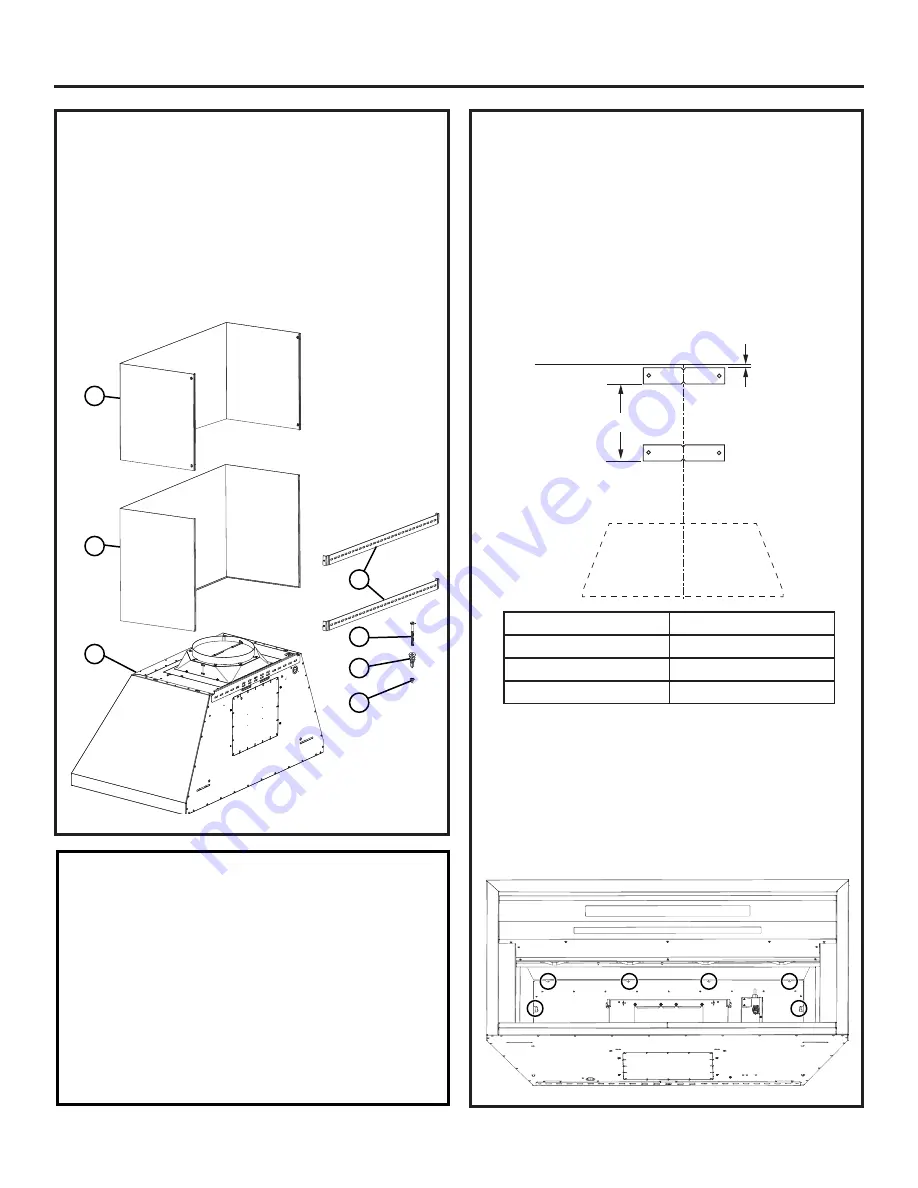
HOOD COMPONENTS

A - Range Hood

B - Screws 

3.1 x 9.5 P013

 (10)

C - Lower Duct Cover (1)
D - Upper Duct Cover (1)
E - Wall Anchors (4) 

F - Wall Bracket (2)

G - Screws 4.2 x 44 PZ1 (4)

INSTALLATION OF DUCT COVER KIT 

(CONT.)

3.  Measure straight down a distance (X) from the 

bottom of the first wall bracket and make a 

horizontal mark. Place the second wall bracket (F) 

above this mark and align the center of the bracket 

with the centerline of the hood. Mark bracket holes. 

Remove the bracket and drill 2 clearance holes 

for wall anchors with 1/16” drill bit. Install the wall 

anchors (E) and secure second wall bracket to the 

wall using screws (G).

4.  Secure the upper duct cover to the wall bracket 

using 4 screws (B). Refer to the installation height 

tables to verify available ceiling heights.

5.  Place the lower duct cover on top of the hood.  

Slightly spread the sides of the cover apart and 

snap to the upper duct cover.  Secure the lower 

duct cover to the hood body from inside the hood 

using 6 screws (B) at locations shown below. 

Installation

CL

1/16"

Ceiling

x

A

C

D

F

G

E

B

INSTALLATION OF DUCT COVER KIT

1.  Finish hood installation as per the hood install 

instructions.

2.  Place wall bracket (F) against the back wall so that 

the top edge is 1/16” from the ceiling and level. 

Align the center of the bracket with the center 

line of the hood and mark bracket holes. 

Use the 

outermost bracket holes to secure to wall. Remove 

the bracket and drill 2 clearance holes for wall 

anchors with 1/16” drill bit. Install the wall anchors 

(E) and secure the bracket to the wall using screws 

(G).

Duct Cover Kit

“X”

8’ Kit

3”

10’ Kit

15-1/2”

12” Kit

25-1/2”

Summary of Contents for ZX8D13SPXX

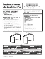
Page 1: ...ct covers to the wall Installation Instructions TOOLS AND MATERIALS REQUIRED Gloves to protect against sharp edges Safety glasses 2 Phillips screwdrivers Drill with 1 8 bits Level Pencil This Kit Includes Upper Duct Cover Lower Duct Cover 2 wall Brackets Hardware package with Screws 3 1 x 9 5 P013 QTY 10 Wall Anchors QTY 4 Screw 4 2 x 44 PZ1 QTY 4 31 2000879 Rev 0 04 21 GEA NOTE Before making any ...

Page 2: ...o the installation height tables to verify available ceiling heights 5 Place the lower duct cover on top of the hood Slightly spread the sides of the cover apart and snap to the upper duct cover Secure the lower duct cover to the hood body from inside the hood using 6 screws B at locations shown below Installation C L 1 16 Ceiling x A C D F G E B INSTALLATION OF DUCT COVER KIT 1 Finish hood instal...

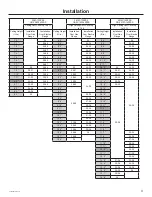
Page 3: ... 24 29 9 9 24 29 7 6 28 30 8 9 24 30 9 10 24 30 7 7 29 31 8 10 24 31 9 11 24 31 7 8 30 30 32 8 11 30 24 32 10 0 30 24 32 7 9 30 31 31 33 9 0 30 31 24 33 10 1 30 31 24 33 7 10 30 32 32 34 9 1 30 32 24 34 10 2 30 32 24 34 7 11 31 33 33 35 9 2 30 33 24 35 10 3 30 33 24 35 8 0 32 34 34 36 9 3 30 34 24 36 10 4 30 34 24 36 8 1 33 35 35 36 9 4 30 35 10 5 30 35 8 2 34 36 36 9 5 30 36 10 6 30 36 8 3 35 36 ...

Page 4: ...4 31 2000879 Rev 0 Notes ...

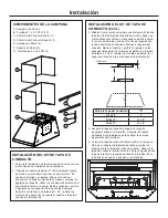
Page 5: ... HERRAMIENTAS Y MATERIALES REQUERIDOS Guantes de protección contra extremos puntiagudos Gafas de seguridad Destornilladores Phillips nº 2 Taladro con brocas de 1 8 Nivel Lápiz Este Kit Incluye Tapa del Conducto Superior Tapa del Conducto Inferior 2 Soportes de Pared Paquete de herramientas con Tornillos de 3 1 x 9 5 P013 Cant 10 Anclajes de Montaje Cant 4 Tornillos de 4 2 x 44 PZ1 Cant 4 31 200087...

Page 6: ...la campana desde la parte interior de la campana usando 6 tornillos B en la ubicaciones que se muestran a continuación INSTALACIÓN DEL KIT DE TAPA DE CONDUCTO 1 Termine la instalación de la campana de acuerdo con las instrucciones de instalación de la campana 2 Coloque el soporte de pared F contra la pared trasera de modo que el extremo superior se encuentre a 1 16 desde el cielorraso y nivelado A...

Page 7: ...8 7 24 28 9 8 24 28 7 5 27 29 8 8 24 29 9 9 24 29 7 6 28 30 8 9 24 30 9 10 24 30 7 7 29 31 8 10 24 31 9 11 24 31 7 8 30 30 32 8 11 30 24 32 10 0 30 24 32 7 9 30 31 31 33 9 0 30 31 24 33 10 1 30 31 24 33 7 10 30 32 32 34 9 1 30 32 24 34 10 2 30 32 24 34 7 11 31 33 33 35 9 2 30 33 24 35 10 3 30 33 24 35 8 0 32 34 34 36 9 3 30 34 24 36 10 4 30 34 24 36 8 1 33 35 35 36 9 4 30 35 10 5 30 35 8 2 34 36 3...

Page 8: ...4 31 2000879 Rev 0 Notas ...

Reviews: