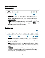
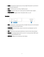
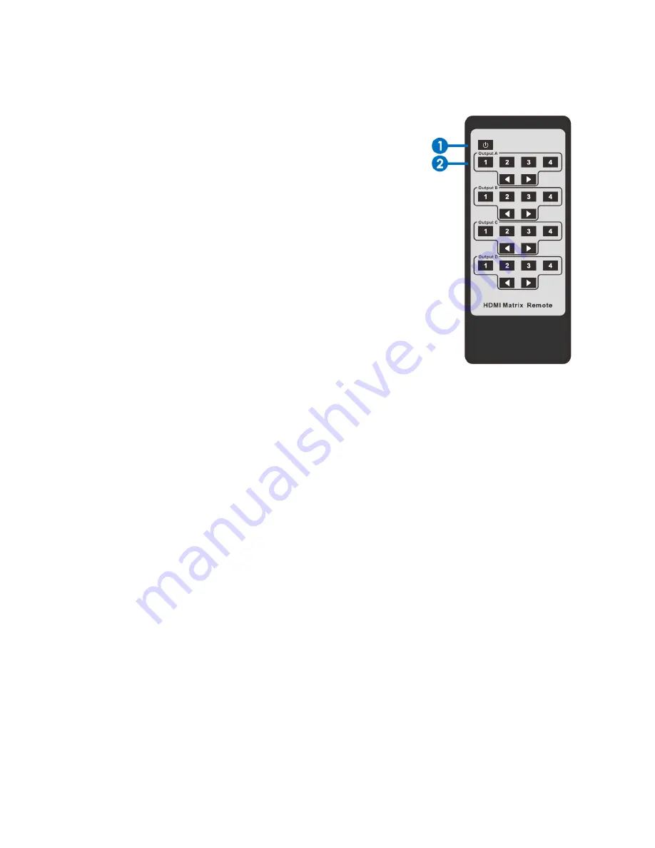
background image

Remote Control 

1.


STANDBY BUTTON: Press the button to put the 
matrix/extender into standby mode or to turn it on. 

2.


SELECTION BUTTONS: Four sets of six buttons for 
selecting which inputs are assigned to each of the 
four outputs. For direct selection, press the number 
corresponding to the desired input in the desired 
output section. You can also use the two arrow 
buttons to cycle to the next or previous input. 


EDID MANAGEMENT 

Prior to installing the matrix/extender, you need to set the EDID DIP switches to control 
the EDID information that will be sent to your source devices. EDID is an acronym for 
Extended Display Identification Data, which is the method by which the display reports its 
maximum resolution and audio capabilities to the source device, so that it can output the 
proper resolution and audio type. If the source device outputs a resolution too high for the 
display, the display will be blank. Similarly, if it tries to output too many audio channels, 
you will only hear part of the audio signal. 
Normally, the source device is connected directly to the display and this operation takes 
place automatically without you even noticing it. However, since this matrix allows 
connection of up to eight displays, each of which may have different capabilities, the 
sources have no way of knowing which resolution and audio settings to use. The EDID DIP 
switches solve this dilemma by providing each source with a fixed capability, so it always 
know which resolution and audio types to output. 
Perform the following steps to set the EDID switches on the matrix/extender, prior to 
installing the system. 

Summary of Contents for 21905

Page 1: ...MONOPRICE Blackbird 4x4 HDMI Matrix Extender with 4 Receivers P N 21905 User s Manual ...

Page 2: ...EATURES 4 CUSTOMER SERVICE 5 PACKAGE CONTENTS 5 PRODUCT OVERVIEW 6 Matrix Front Panel 6 Matrix Rear Panel 6 Receivers 7 Remote Control 8 EDID MANAGEMENT 8 INSTALLATION 10 SPECIFICATIONS 13 REGULATORY COMPLIANCE 13 Notice for FCC 13 Notice for Industry Canada 14 ...

Page 3: ...rom the power outlet and allow it to fully dry before reapplying power Do not touch the device the power cord or any other connected cables with wet hands Do not expose this device to excessively high temperatures Do not place it in on or near heat sources such as a fireplace stove radiator etc Do not leave it in direct sunlight Ensure that power is turned off and disconnected before making any el...

Page 4: ...l option It supports IR extension so you can control the source devices from the remote locations FEATURES Distributes any of four HDMI source devices to any of four pairs of outputs Simultaneously supports local displays and displays connected to remote receivers Supports video resolutions up to 1080p 60Hz Can extend 1080p video signals to distances up to 164 feet 50 meters over a single Cat6 Eth...

Page 5: ...site www monoprice com during normal business hours Mon Fri 5am 7pm PT Sat Sun 9am 6pm PT or via email at support monoprice com PACKAGE CONTENTS Please take an inventory of the package contents to ensure you have all the items listed below If anything is missing or damaged please contact Monoprice Customer Service for a replacement 1x Blackbird 4x4 HDMI matrix extender 4x Receivers 1x AC power ada...

Page 6: ...n to assign the displayed input to the selected output Matrix Rear Panel 1 OUTPUTS Four pairs of HDMI and RJ45 video outputs Connect a local display to the HDMI port using an HDMI Cable or connect a remote receiver using a Cat6 Ethernet cable or both 2 INPUT Four HDMI inputs for connecting video source devices and four 3 5mm IR outputs for connecting an IR transmitter for remote control of each vi...

Page 7: ...rix on or off Receivers 1 IR IN 3 5mm jack for connecting one off the included IR receivers for controlling the source devices from the remote location 2 POWER LED The LED illuminates when the receiver is receiving power over the Ethernet cable 3 CAT RJ45 jack for connecting the Cat6 Ethernet cable from the matrix extender 4 LINK LED The LED illuminates when the receiver is receiving a stable HDMI...

Page 8: ... resolution and audio capabilities to the source device so that it can output the proper resolution and audio type If the source device outputs a resolution too high for the display the display will be blank Similarly if it tries to output too many audio channels you will only hear part of the audio signal Normally the source device is connected directly to the display and this operation takes pla...

Page 9: ... with 7 1 channel audio Based on this information you would need to set the EDID for 720p 1080i video and 2 channel audio 3 Locate the row on the following table that matches the minimum capabilities of your displays and set the DIP switches accordingly Note that the DIP switch down position is 0 and the up position is 1 Video Resolution Audio Type DIP Switches 720p 1080i 2 channel 0 0 0 0 720p 10...

Page 10: ...OUTPUT D 1 1 1 1 INSTALLATION Perform the following steps to install the matrix extender system 1 If you have not already done so set the EDID DIP switches on the rear panel to match the minimum capabilities of the displays you will be connecting 2 Ensure that all equipment to be connected is powered off and unplugged from its power source ...

Page 11: ... position the IR eye where it can receive signals from the remote control Alternatively if you want to control the remote displays from the source location plug each of the included IR receivers into the IR OUT jacks on the matrix extender then position the IR eyes where they can receive signals from the remote controls 8 Optional If you want to control the source devices from the remote display l...

Page 12: ...11 Using a Cat6 Ethernet cable not included plug one end into the CAT RJ45 jack on one of the receivers then plug the other end into one of the UTP OUTPUTS on the matrix extender Repeat for up to three additional remote receivers 12 Ensure that the POWER SWITCH on the matrix extender is in the OFF position 0 13 Plug the DC barrel connector on the included AC power adapter into the POWER connector ...

Page 13: ...non condensing Dimensions 17 3 x 7 9 x 1 8 440 x 200 x 45 mm Weight 4 0 lbs 1820g REGULATORY COMPLIANCE Notice for FCC This device complies with Part 15 of the FCC rules Operation is subject to the following two conditions 1 this device may not cause harmful interference and 2 this device must accept any interference received including interference that may cause undesired operation Modifying the ...

Page 14: ...rmful interference to radio or television reception which can be determined by turning the equipment off and on the user is encouraged to try to correct the interference by one or more of the following measures Reorient or relocate the receiving antenna Increase the separation between the equipment and receiver Connect the equipment into an outlet on a circuit different from that to which the rece...

Reviews: