background image

29 

Interface Screen 


The Interface screen allows you to change various text labels. For example, you may want 
to change the name for Input 1 to DVD, so that you don't have to remember that Input 1 is 
the DVD player. 
To change one or more labels, click in the appropriate field(s) and type in the new label, 
then click the Confirm button to save the changes or the Cancel button to abort the 
changes. 
 

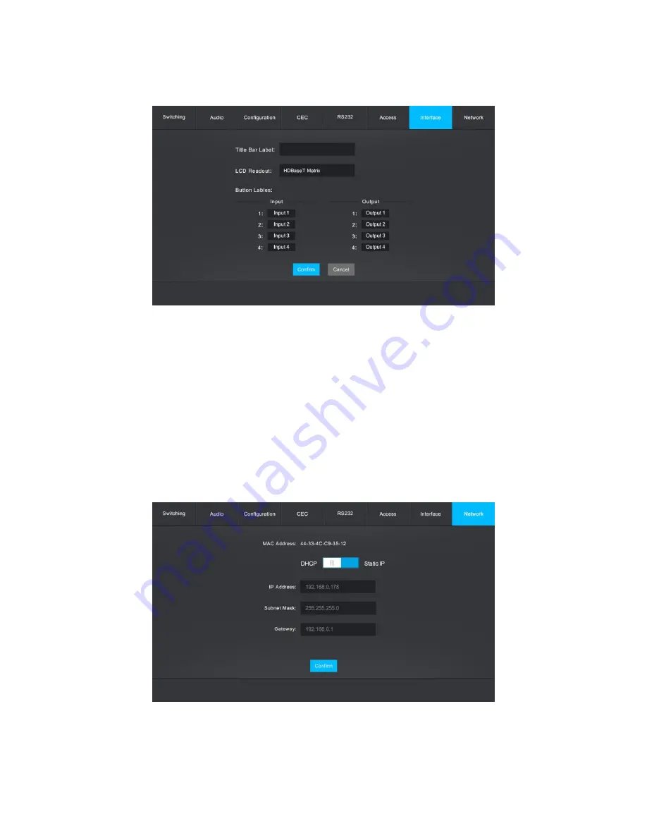
Network Screen 


The Network screen allows you to change the network protocol and allows you to set the 
IP Address, Subnet Mask, and Gateway addresses. 

Summary of Contents for 27841

Page 1: ...Blackbird 4K HDBaseT 4x4 HDMI Matrix P N 27841 User s Manual ...

Page 2: ... 8 Receiver Front Panel 9 Receiver Rear Panel 10 Remote Control 11 SAMPLE CONNECTION DIAGRAM 12 IR PASS THROUGH 12 Control Local Input Device From Local 12 Control Local Input Device From Remote 14 Control Remote Device From Local 15 BUTTON CONTROL 16 Switching 16 EDID Management 16 Inquiry Mode 18 Recall Preset 19 GUI CONTROL 20 Switching Screen 21 Audio Screen 22 ...

Page 3: ...n 28 Interface Screen 29 Network Screen 29 CEC BUTTONS 30 GUI UPDATE 31 RS 232 CONTROL 32 Control Matrix From Local 32 Control Matrix From Remote 32 Control Remote Third Party Device From Local 33 Control Local Third Party Device From Remote 33 RS 232 COMMANDS 34 System Commands 35 Signal Switching 37 Preset Management 39 Output Audio Control 39 EDID Configuration 40 HDCP Compliance 42 Baud Rate S...

Page 4: ...diately unplug it from the power outlet and allow it to fully dry before reapplying power Do not touch the device the power cord or any other connected cables with wet hands Do not subject the product to extreme force shock or fluctuations in temperature or humidity Do not expose this device to excessively high temperatures Do not place it in on or near heat sources such as a fireplace stove radia...

Page 5: ...ot attempt to open service or modify this device INTRODUCTION The Blackbird 4K HDBaseT 4x4 HDMI Matrix is a professional level matrix switch and HDMI extender It features four HDMI inputs and four sets of HDMI and HDBaseT outputs allowing for both local and remote displays It extends 4K 60Hz video signals to distances up to 131 feet 40 meters and 1080p 60Hz signals to distances up to 229 feet 70 m...

Page 6: ...wing for both local and remote displays for each output channel Features comprehensive EDID management Supports bi directional IR and RS 232 extension Supports front panel IR remote control RS 232 and TCP IP control options CUSTOMER SERVICE The Monoprice Customer Service department is dedicated to ensuring that your ordering purchasing and delivery experience is second to none If you have any prob...

Page 7: ...astic feet 8x Receiver mounting ears 8x Receiver mounting ear screws 4x IR receivers 4x IR transmitters 1x 3 pin to DB9 RS 232 cable 13x 3 pin terminal blocks 1x AC power cord 1x User s manual PRODUCT OVERVIEW Matrix Front Panel 1 LCD SCREEN Displays the real time operating status 2 PWR The LED illuminates red when power is applied 3 IR The LED illuminates red when the matrix receives an IR signal...

Page 8: ...ss and hold the ENTER button for 3 seconds to enter Inquiry Mode RECALL Allows selection and recall of a previously saved preset layout Matrix Rear Panel 1 INPUT Four HDMI ports for connecting video source devices 2 IR IN Five 3 5mm jacks for connecting IR receivers 3 IR OUT Five 3 5mm jacks for connecting IR transmitters 4 OUTPUT Four sets of RJ45 jacks and HDMI ports for connecting the included ...

Page 9: ...itch for turning the matrix on and off 9 GROUND Ground connector Receiver Front Panel 1 CTRL UPDATE Switch for selecting the behavior of the RS 232 connection When in the CTRL position the RS 232 connection carries the RS 232 pass through data When in the UPDATE A position you can update the Valens IC by connecting your PC to the RS 232 connection and running a batch bat file When in the UPDATE B ...

Page 10: ... block for connecting an RS 232 control or pass through device 3 IR IN 3 5mm jack for connecting an IR receiver 4 IR OUT 3 5mm jack for connecting an IR transmitter 5 HDBT IN RJ45 jack for connecting the Ethernet cable from the matrix 6 DC 12V DC barrel connector for connecting an AC power adapter ...

Page 11: ...ns for menu manipulation The ALL button selects all inputs or all outputs The EDID button enables an input to manually capture and learn the EDID of an output device The CLEAR button cancels a command in progress Momentarily pressing the ENTER button accepts the command in progress while holding it for 3 seconds enters Inquiry Mode Note that the buttons on the remote control correspond directly to...

Page 12: ... illustrate possible configurations The kit comes with four IR receivers and four IR transmitters Some connections require additional receivers and or transmitters which will need to be obtained separately Control Local Input Device From Local By default there is a one to one relationship between the IR OUT port on the matrix and the HDMI input When you switch an HDMI input the corresponding IR OU...

Page 13: ...nto IR OUT 3 as shown in the diagram below The same standard applies when you have one HDMI input connected to multiple HDBaseT outputs For example if you have HDMI input 3 connected to HDBaseT output 2 3 and 4 plug an IR receiver into IR IN 2 IR IN 3 and IR IN 4 then plug an IR transmitter into IR OUT 3 as shown in the diagram below ...

Page 14: ... plug an IR receiver into the IR IN jack on the receiver then plug an IR transmitter into IR OUT 3 on the matrix as shown in the diagram below Similarly you can control all local input devices by plugging an IR transmitter into the IR OUT ALL OUT jack on the matrix In this case you must have an IR receiver plugged into the IR IN jack on each of the connected HDBaseT receivers as shown in the diagr...

Page 15: ...into the IR IN 3 jack on the matrix then plug an IR transmitter into the IR OUT jack on the receiver as shown in the diagram below Similarly you can control all remote displays by plugging an IR receiver into the IR IN ALL IN jack on the matrix In this case you must have an IR transmitter plugged into the IR OUT jack on each connected HDBaseT receiver as shown in the diagram below ...

Page 16: ...xample to connect HDMI input 1 to HDBaseT outputs 2 3 and 4 press the INPUT 1 button then press the OUTPUT 2 OUTPUT 3 and OUTPUT 4 buttons and finally press the ENTER button The indicators in the INPUT 1 OUTPUT 2 OUTPUT 3 OUTPUT 4 and ENTER buttons will blink 3 times To make a connection between an HDMI input and all HDBaseT outputs press an INPUT button then press the ALL button and finally press...

Page 17: ... disconnect the Ethernet cable from the HDBaseT output To copy the EDID information from one display to one source first press the EDID button then press an INPUT button followed by an OUTPUT button and finally press the ENTER button to confirm For example to copy the EDID information from output 4 to source 2 press the EDID button then press the INPUT 2 button followed by the OUTPUT 4 button and ...

Page 18: ...ngs to all source devices first press and hold the EDID button for 3 seconds then press the ALL button then use the LEFT OUTPUT 2 and RIGHT OUTPUT 4 buttons to select a preset and finally press the ENTER button to confirm The EDID ALL LEFT RIGHT and ENTER buttons will blink 3 times Inquiry Mode Inquiry Mode allows you to check the connection status of the matrix as a whole or of a single output To...

Page 19: ...For example to see the current connection for output 2 first press and hold the ENTER button for 3 seconds then press the OUTPUT 2 button The LCD screen will show the following display and the corresponding INPUT and OUTPUT buttons will illuminate for 3 seconds Recall Preset You can create and save up to nine layout presets using RS 232 commands or using the built in web GUI Once saved you can rec...

Page 20: ...ernet network The matrix has the following default IP settings IP Address 192 168 0 178 Subnet Mask 255 255 255 0 To display the GUI open an internet browser then type 192 168 0 178 into the address field and press the ENTER key You will see the following screen in your browser Type the User Name and Password into the appropriate fields then click the Login button to log into the GUI The default U...

Page 21: ...on of the Output 2 column and the Input 1 row The Scene buttons allow you to create and save layout presets which can be recalled using the RECALL button on the front panel as described above To save a given layout first create connections for each output as desired then click one of the Scene buttons and finally click the Save button to save the layout To recall a previously saved layout click th...

Page 22: ...our coaxial audio jacks on the rear panel Each output can be set to use the audio stripped from the corresponding numbered HDMI source device or the corresponding HDBaseT output Click the buttons in the Volume column to turn audio muting on or off for the corresponding output HDCP Configuration Screen ...

Page 23: ...uration screen allows you to turn HDCP on or off for each output Click the radio button in the On or Off column next to the desired output Click the Confirm button to save the changes or click the Cancel button to abort the changes ...

Page 24: ...click one or more of the buttons in the Input column Alternatively click the All button to select all Inputs Next click one of the four buttons in the Output column Finally click the Confirm button to make the change or the Cancel button to abort the change EDID Setting Configuration Screen The EDID Setting tab on the Configuration screen allows you to assign one of the predefined EDID settings to...

Page 25: ... the change HDMI Input CEC Screen The HDMI Input tab on the CEC screen allows you to issue control commands to one of the inputs using the Consumer Electronics Control CEC feature of the HDMI specification To control one of the HDMI source devices first click the button in the Input column corresponding to the source you want to control Next click any of the buttons on the right to issue the indic...

Page 26: ...rst click the button in the Output column corresponding to the display you want to control Next click any of the buttons on the right to issue the indicated command Refer to the CEC BUTTONS section for an explanation of the meaning of each of the icons used on the buttons HDMI Output CEC Screen The HDMI Output tab of the CEC screen allows you to control one of the displays connected to a local HDM...

Page 27: ...ol an RS 232 device connected to one of the HDBaseT receivers first click one of the buttons in the Port section corresponding to the HDBaseT receiver with the device you want to control Next click one of the buttons in the Baud Rate section to set the communications rate between the HDBaseT receiver and the RS 232 device You are now ready to send a command To send the command first determine whet...

Page 28: ...ds are admin and user To change either password click inside the field and type a new password then click the Confirm button to save the change or the Cancel button to abort the change To lock the front panel controls click the ON or OFF side of the Front Panel Lock control then click the Confirm button to save the change or the Cancel button to abort the change ...

Page 29: ...to remember that Input 1 is the DVD player To change one or more labels click in the appropriate field s and type in the new label then click the Confirm button to save the changes or the Cancel button to abort the changes Network Screen The Network screen allows you to change the network protocol and allows you to set the IP Address Subnet Mask and Gateway addresses ...

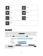
Page 30: ...nges To change the IP Address Subnet Mask or Gateway click in the field and type in a new address then click the Confirm button to save the changes CEC BUTTONS The following table identifies the icons used in the CEC buttons on the CEC screens in the GUI Power on Power off Stop Pause Play Menu Previous Next Fast reverse Fast forward Volume down Volume up ...

Page 31: ...178 100 into the address bar of a web browser The login User Name and Password are the same as that of the control GUI The default User Name is user and the default Password is also user Once on the screen click the Administration entry then click the Upload Program entry Click the Choose File button then locate and select the update file Finally click Apply to begin the update process ...

Page 32: ...nel then plug the other end into an available serial port on your PC as shown in the diagram below Control Matrix From Remote To control the matrix from a remote location plug one end of the included 3 pin to DB9 RS 232 Cable into the RS232 connector on one of the HDBaseT receivers then plug the other end into an available serial port on your PC as shown in the diagram below ...

Page 33: ...lug the other end into an available serial port on your PC as shown in the diagram below Control Local Third Party Device From Remote To control a local third party device from one of the HDBaseT receivers first determine which receiver you will be connecting to 4 in the diagram below Next plug one end of the included 3 pin to DB9 RS 232 Cable into the RS232 connector on the HDBaseT receiver then ...

Page 34: ...gnals through to a third party device It supports serial communications rates of 2400 4800 9600 default 19200 38400 57600 or 115200 baud The RS 232 communications protocol is as follows Baud Rate 9600 default Data Bits 8 Stop Bits 1 Parity None Download and install a third party RS 232 control software such as CommWatch exe whose interface is shown below as an example ...

Page 35: ...mmands System Commands Command Function Feedback Type Report matrix model 27841 Name Report matrix name HDBaseT Matrix Lock Lock the front panel buttons System Locked Unlock Unlock front panel buttons System Unlock Version Report software version V1 0 0 ...

Page 36: ...02 02 02 PWON Power the system on PWON PWOFF Powers the system off PWOFF STANDBY Put the system in standby mode STANDBY 9961 Report the system lock status System Locked System UnLock 9962 Report the system power status PWON PWOFF STANDBY RemoteCtrMcu x Enable disable the remote control mode that the matrix can be controlled from a remote PC x 1 or 0 RemoteCtrMcu Open 0911 Reset to factory default ...

Page 37: ...s All Closed x Switch input x to output x x 1 4 01 Through x Switch off output x x 1 4 01 Closed x Switch on output x x 1 4 01 Open Out 01 02 03 04 In 01 01 01 01 All Switch on all outputs All Open Out 01 02 03 04 In 01 01 01 01 x V y Switch input x to one or more outputs y Separate multiple channels with a comma x 1 4 y 1 4 AV 01 01 AV 01 02 AV 01 03 Status x Report the input channel on output x ...

Page 38: ...nnection status of all inputs Y means the corresponding input port is connected to a source device N means it is not In 01 02 03 04 Connect Y Y Y N 9972 Report the connection status of all outputs Y means the corresponding output port is connected to an output device N means it is not Out 01 02 03 04 Connect Y Y Y Y 9975 Report the switching status Out 01 02 03 04 IN 01 02 03 01 ...

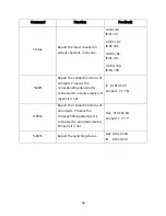
Page 39: ...rol Command Function Feedback COAX x MU UM Mute or unmute the coaxial audio output x x 01 04 Use MU for mute or UM for unmute COAX01MU ss AnlogAudio x MU UM Mute or unmute the analog audio output x x 01 04 Use MU for mute or UM for unmute AnlogAudio01UM 9977 Report the output audio status COAX010 COAX020 COAX030 COAX040 COAX01UM COAX02UM COAX03UM COAX04UM AnlogAudio01UM AnlogAudio02UM AnlogAudio03...

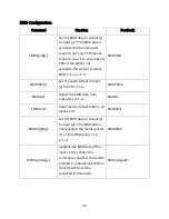
Page 40: ...t the audio format of input x to PCM x 1 4 EDIDPCM4 EDIDG x Report the EDID data from output x x 1 4 EDIDG2 EDIDMInit Reset factory default EDID to all input ports EDIDMInit EDIDM x B y Set the EDID data of output x to input y If the EDID data is not available the matrix will set it to initial EDID data x 1 4 y 1 4 EDIDM1B4 EDIDUpgrade x Upgrade the EDID data of the input port x When the command i...

Page 41: ... Dolby DTS 6 4K 60Hz 4 2 0 PCM Dolby DTS 7 4K 60Hz 4 4 4 2D PCM Dolby DTS EDIDIN 1 0 UpgradeIntEDID y Upgrade the embedded EDID y y 1 7 When the matrix gets the command it will show a message to send EDID file bin file The operation will be canceled in 10 seconds UpgradeIntEDID3 GetInPortEDID x Report the EDID of input x x 1 4 GetInPortEDID1 GetIntEDID x Report the embedded EDID y y 1 7 GetIntEDID...

Page 42: ...DCP compliance status X 01 04 or ALL Z 0 1 O 1 1 0801 Auto HDCP management mode 0801 9973 Report the HDCP status of all inputs Y means the input AV signal has HDCP data N means it does not In 01 02 03 04 HDCP Y Y Y Y 9974 Report the HDCP status of all outputs Y means the output AV signal has HDCP data N means it does not Out 01 02 03 04 HDCP Y Y Y Y ...

Page 43: ...aud rate of the matrix to 19200 Set Local RS232 baudrate is 19200 Baudrate 38400 Set the serial baud rate of the matrix to 38400 Set Local RS232 baudrate is 38400 Baudrate 57600 Set the serial baud rate of the matrix to 57600 Set Local RS232 baudrate is 57600 Baudrate 115200 Set the serial baud rate of the matrix to 115200 Set Local RS232 baudrate is 115200 CEC Control Commands If the input source...

Page 44: ...ESS CECI port 01 UP direction CEC_IN_01_SEND_SUCCESS CECI port 02 DOWN direction CEC_IN_01_SEND_SUCCESS CECI port 03 LEFT direction CEC_IN_01_SEND_SUCCESS CECI port 04 RIGHT direction CEC_IN_01_SEND_SUCCESS CECI port 0A Enter main menu CEC_IN_01_SEND_SUCCESS CECI port 0D Exit menu CEC_IN_01_SEND_SUCCESS CECI port 41 Volume up CEC_IN_01_SEND_SUCCESS CECI port 42 Volume down CEC_IN_01_SEND_SUCCESS C...

Page 45: ...port 41 Volume up CEC_OUT_01_SEND_SUCCESS CECO port 42 Volume down CEC_OUT_01_SEND_SUCCESS CECO port 43 Mute CEC_OUT_01_SEND_SUCCESS CECO port 6C Power off CEC_OUT_01_SEND_SUCCESS CECO port 6D Power on CEC_OUT_01_SEND_SUCCESS TROUBLESHOOTING Problem Potential Causes Potential Solutions Output image has video noise Bad quality of connecting cable Try another cable Failed or loose connection Ensure ...

Page 46: ...not work normally The HDMI cable is broken at the output end Use a known good High Speed HDMI Cable Static becomes stronger when connecting the video connectors Bad grounding Ensure the matrix is properly grounded Cannot control the matrix by PC through an RS 232 connection Wrong RS 232 communications parameters Use the correct RS 232 communication parameters Cannot control the matrix using the fr...

Page 47: ...website www monoprice com during regular business hours 7 days a week You can also get assistance through email by sending a message to tech monoprice com SPECIFICATIONS Matrix Model 27841 Inputs 4x HDMI Outputs 4x HDMI 4x HDBaseT Maximum Input Resolution 4K 60Hz 4 4 4 Maximum HDMI Output Resolution 4K 60Hz 4 4 4 Maximum HDBaseT Output Resolution 4K 60Hz 4 2 0 Bandwidth 18 Gbps HDMI Version 2 0 HD...

Page 48: ...perature 14 131 F 10 55 C Relative Humidity 10 90 RH non condensing Dimensions 17 1 x 1 7 x 13 4 436 x 44 x 340 mm Weight 7 1 lbs 3 2 kg Receivers Inputs 1x HDBaseT Outputs 1x HDMI Maximum Resolution 4K 60Hz 4 4 4 Bandwidth 18 Gbps Transmission Method HDBaseT Maximum Transmission Distance 4K 60Hz up to 131 feet 40 meters 1080p 60Hz up to 229 feet 70 meters HDMI Version 2 0 HDCP Version 2 2 Input P...

Page 49: ...High Definition Multimedia Interface are trademarks or registered trademarks of HDMI Licensing LLC in the United States and other countries HDBaseT and the HDBaseT Alliance logo are trademarks of the HDBaseT Alliance Dolby and the double D symbol are registered trademarks of Dolby Laboratories DTS is a registered trademark and the DTS logos and Symbol are trademarks of DTS Inc Blu ray Disc and Blu...

Reviews: