


32
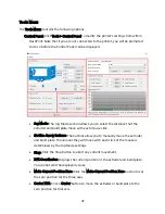
Extruder
Selects the right or left extruder for printing.
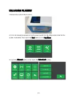
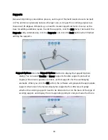
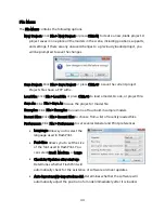
Loading a File
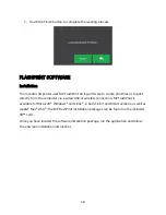
FlashPrint supports six different ways to load a model or Gcode file, as outlined below.
Click the Load icon on the main interface, then select the file.
Drag and drop the file onto the main interface.
Click File > Load File, then select the file.
Click File > Load Examples to load one of the sample files.
Click File > Recent Files, then select the file from the list of recently used files.
Drag and drop the file onto the FlashPrint icon on the desktop to launch FlashPrint
and load the file.
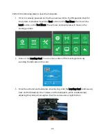
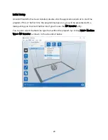
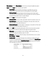
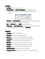
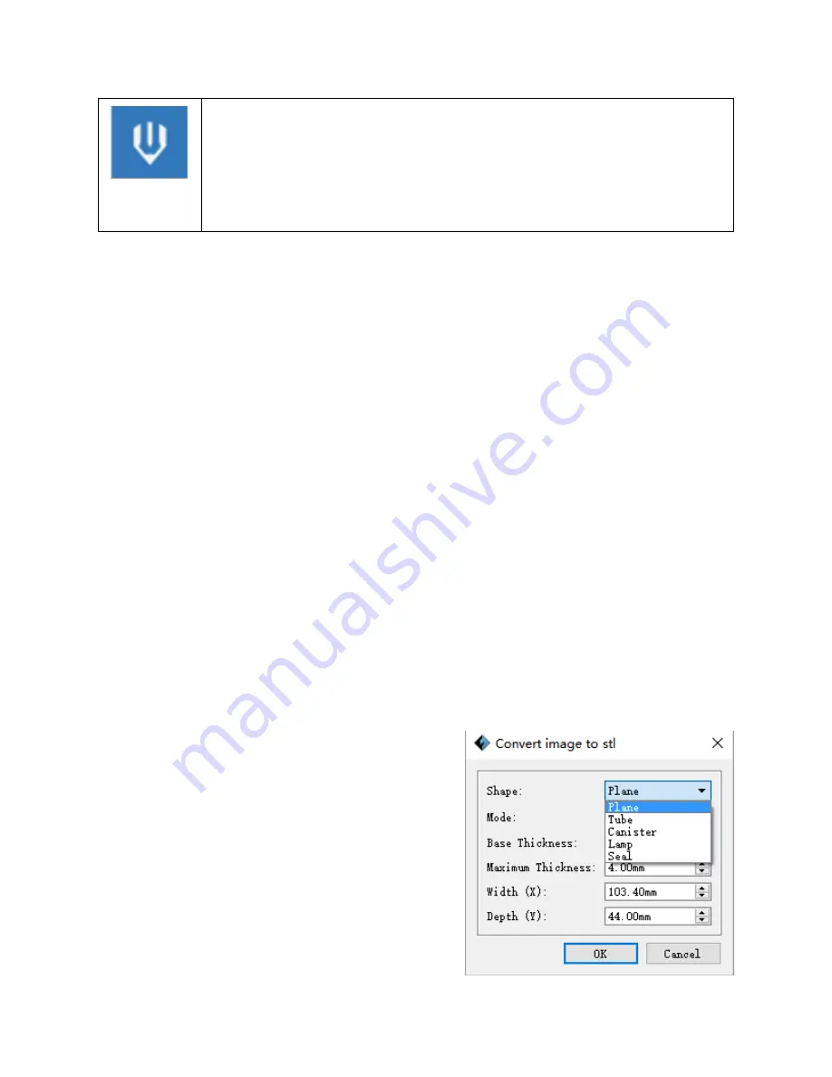
Generating a Model
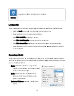
FlashPrint can generate a 3D model file from a .PNG, .JPG, .JPEG, or .BMP image file. When
you load the image file, the following dialog box will be displayed, which allows you to set
several model parameters.
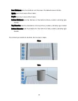
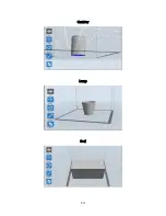
Shape: Determines the basic shape of the
model. You can select Plane, Tube, Canister,
Lamp, or Seal basic shapes.
Mode: Selects whether the light or dark
portions of the image will be the high
points of the model.
Maximum Thickness: Sets the Z value of the
model.


