background image


58 

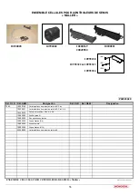
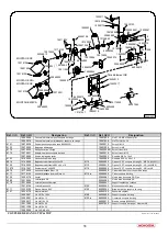
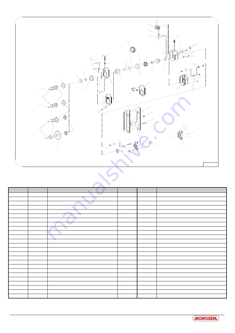
10219106

10075031

20049910

20049920

10075031

10075030

10174130

10219092

66004995

10075028

65040109

10160009

10075029

10159050

65009362

10160034

66004408

10511058

10600010

20049950

66005910

10500091

10040064

66005910

10591905

10174030

20049960

65009363

10230175

10200174

10230100

10511058

10500061

10601008

10511003

10591928

10590066

10502017

10603010

10620088

10161047

10603010

10511003

10601010

10603008R

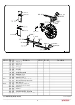
Tête d'élément NX

20065981

10500091

10620042

10620042

10500091

20065982

10219106

10219106

20049900

66007040

P04010031

10040074

20069251

10075056

10219004

10200238

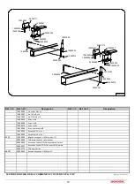
MONTAGE NC

MONTAGE NG+
MONTAGE NX

MONTAGE MECA


COUPURE DE RANGS TIP & TOP


Mise à jour le 19/01/2016 

Réf. 

OLD

  Réf. 

NEW


Désignation 

Réf. 

OLD

  Réf. 

NEW


Désignation 


10040064 

Couvercle aluminium pour coupure de rangs 


10591905 

Vis STHC M8 x 10 bout plat 


10040074 

Couvercle aluminium injecté pour coupure de rangs 


10591928 

Vis TFHC M5 x 30 

6121 

10075028 

Porte pignon coupure de rang (40090352) 


10600010 

Ecrou H M10 

6122 

10075029 

Bague de débrayage 


10601008 

Ecrou Hm M8 

6116 

10075030 

Rondelle verrou circlips 


10603008R 

Ecrou frein H M8 

6112 

10075031 

Entretoise pignon coupure de rang 


10603010 

Ecrou frein H M10 


10075056 

Axe de réglage de levier 


10620042 

Rondelle Ø6.5 x 18 x 2 

6123 

10159050 

Ressort coupure de rang  


10620088 

Rondelle Ø10.5 x 20 x 1.5 

6914 

10160009 

Bague autolubrifiante 30x38x30 

6115 

20049900 

Disque 30 DT coupure de rang EL : MECA (40090311) 

6125 

10160034 

Bague autolubrifiante Ø35 x 44 x 10 

6113 

20049910 

Pignon 16 DT coupure de rang EL : NC (40090313) 

11579 

10161047 

Roulement réf, 6006 ZZ 

6114 

20049920 

Disque 18 DT coupure de rang EL : NG+ et NX  

6915 

10174030 

Anneau élastique Øext. 30 


20049950 

Carter aluminium pour coupure de rangs 

6117 

10174130 

Anneau élastique inverse Øext. 30 

6119.a 

20049960 

Carter coupure de rang  

6126 

10200174 

Levier  


20065981 

Vis de bras de couple NG Plus 

6089 

10219004 

Joint torique Ø8 


20065982 

Vis de bras de couple NX 

6118 

10219092 

Joint d’étanchéité moyeu 


20069251 

Support capteur de rotation 


10219106 

Joint d’étanchéité 

6124 

65009362 

Moyeu coupure de rang  

6111 

10230100 

Presse étoupe M12 

6129 

65009363 

Bride de fixation coupure de rang  

6127 

10230175 

Electro-aimant  


65040109 

Ensemble capteur 


10500061 

Vis H 3/8 x 10 Zn 

6168 

66004408 

Support coupure de rang 


10500091 

Vis H M6 x 12 

6120.a 

66004995 

Couvercle coupure de rang  


10502017 

Vis H M10 x 30 


66005910 

Bras de couple (65009485) 


10511003 

Vis H M6 x 60 


66007040 

Support coupure de rangs – élément NX 


10511058 

Vis H M8 x 35 


10590066 

Vis CHC M5 x 30  


Summary of Contents for CS 6200-24

Page 1: ...2017 Réf 10640155 COMPAGNIE COMMERCIALE RIBOULEAU NOTICE CONSOLE CS 6200 24 SEED MONITOR CS 6200 24 Säüberwachung CS CS 6200 24 NOTICE D UTILISATION USERS MANUAL BEDIENUNGS ANLEITUNG www monosem com ...

Page 2: ...d the telephone number on the last page of this manual The identification and year of manufacture of your planter are on the central gear box With the aim of continuously improving our products we reserve the right to modify our equipment without notice As a result some elements may differ from those describeb in these instructions ORIGINAL INSTRUCTIONS Lesen Sie sich vor Montage und Benutzung auf...

Page 3: ...1 Notice d utilisation ...

Page 4: ...4 2 2 PRESELECTION D ARRET PERMANENT DE RANG 22 25 4 2 3 RESULTATS 2 26 27 4 3 ECRANS DONNEES MACHINE 28 4 3 1 DONNEES MACHINE 1 28 29 4 3 2 DONNEES MACHINE 2 32 33 34 4 3 3 DONNEES MACHINE 3 36 37 4 3 3 CALIBRAGE DU CAPTEUR DE VITESSE 38 4 4 ECRANS DE SERVICE 42 4 4 1 SERVICE 1 42 4 4 2 SERVICE 2 43 4 4 3 SERVICE 3 44 45 5 ANNEXE 46 5 1 DONNEES TECHINQUES CALCULATEUR DE TRAVAUX FUJITSU 46 47 5 2 ...

Page 5: ...ELECTION FOR PERMANENT UNIT DEACTIVATION 23 25 4 2 3 RESULTS 2 26 27 4 3 MACHINE DATA SCREENS 28 4 3 1 MACHINE DATA 1 28 30 4 3 2 MACHINE DATA 2 32 33 34 4 3 3 MACHINE DATA 3 36 37 4 3 3 CALIBRATION OF THE SPEED SENSOR 39 4 4 SERVICE SCREENS 42 4 4 1 SERVICE 1 42 4 4 2 SERVICE 2 43 4 4 3 SERVICE 3 44 45 5 APPENDIX 46 5 4 TECHNICAL SPECIFICATIONS FUJITSU JOB COMPUTER 46 47 5 5 GLOSSARY 49 5 6 ABBRE...

Page 6: ...2 2 VORWAHL FÜR PERMANENTE AGGREGATABSCHALTUNG 24 25 4 2 3 ERGEBNISSE 2 26 27 4 3 MASCHINENDATEN MASKEN 28 4 3 1 MASCHINENDATEN 1 28 31 4 3 2 MASCHINENDATEN 2 32 33 34 4 3 3 MASCHINENDATEN 3 36 37 4 3 3 KALIBREIRUNG DES GESCHWINDIGKEITSSENSORS 40 4 4 ECRANS DE SERVICE 42 4 4 1 SERVICE 1 42 4 4 2 SERVICE 2 43 4 4 3 SERVICE 3 44 45 5 ANHANG 46 5 1 TECHNISCHE DATEN JOBRECHNER FUJITSU 46 47 5 2 GLOSSA...

Page 7: ...fitted with the latest state of technology More than ten years of experience in developing CAN bus components have had a considerable impact in this regard Should you have any questions regarding one of the terminals please consult the installation and operating instructions of the respective terminal 1 Einführung Mit dem Jobrechner Einzelkorn Drille ist Ihre Maschine mit der neuesten Technologie ...

Page 8: ...pecter ce symbole signalant les mesures de sécurité importantes Il signifie Attention Soyez vigilant Il s agit de votre sécurité Lisez la notice d utilisation avant d utiliser pour la première fois le système 2 Safety Instructions 2 1 Disclaimer The seed drill job computer is intended solely for agricultural use The manufacturer may not be held responsible for any other use or installation The man...

Page 9: ...endung gehört auch die Einhaltung der vom Hersteller vorgeschriebenen Betriebs und Instandhaltungsbedingungen Die einschlägigen Unfallverhütungsvorschriften sowie die sonstigen allgemein anerkannten sicherheitstechnischen industriellen medizinischen und straßenverkehrsrechtlichen Regeln sind einzuhalten Eigenmächtige Veränderungen am Gerät schließen eine Haftung des Herstellers aus 2 2 Sicherheits...

Page 10: ...pecter les mesures préventives et les instructions de sécurité suivantes N enlevez pas de mécanismes ou panneaux de sécurité Avant d utiliser l appareil veuillez lire et bien comprendre cette notice Il est également important que les autres utilisateurs lisent et comprennent ce manuel Coupez l alimentation de courant retirer la prise de l équipement de base lors de la maintenance ou de l emploi du...

Page 11: ...licher Garantieansprüche Betätigen Sie die Tasten mit Ihrer Fingerkuppe Vermeiden Sie es die Fingernägel zu benutzen Sollte irgendein Teil dieser Anleitung nach dem Lesen Ihnen weiterhin unverständlich bleiben setzen Sie sich zwecks weiterer Erklärungen vor dem Einsatz des Gerätes mit dem Händler oder mit dem Müller Elektronik Kundendienst in Verbindung Lesen Sie sorgfältig alle Sicherheitsanweisu...

Page 12: ...e job computer alone is not sufficient for operating the seed drill The job computer may only be used if it is attached to one of the aforementioned terminals mounted on the tractor in the basic setup 3 Übersicht und Inbetriebnahme Der Jobrechner ist allein nicht ausreichend um die Einzelkorn Drille zu bedienen Der Jobrechner kann nur benutzt werden wenn er über eine Grundausrüstung an eines der o...

Page 13: ...0 24 mit Traktor Grundausrüstung mit Geschwindigkeitssensor Jobrechnern und Kabelbäumen Die Grundausrüstung versorgt das CS 6200 24 mit Spannung stellt die Verbindung zur Maschine her und bietet einen Anschluss für einen Geschwindigkeitssensor am Traktor Das Anschlusskabel 5 die Maschinen Jobrechner 7 und 8 und die zugehörigen Kabelbäume 9 und 10 gehören zur Maschine Hier sind je nach Ausbaustufe ...

Page 14: ...12 4 Ecrans La structure des écrans est représentée dans ce schéma passage à l écran suivant et écran précédent ...

Page 15: ...13 4 Screens This page outlines the screen structure In doing we have decided not to include a presentation of the softkeys back to work screen and previous screen ...

Page 16: ...14 4 Masken Auf dieser Seite ist die Maskenstruktur dargestellt Dabei wurde auf die Darstellung der Tasten zurück zur Arbeitsmaske und vorherige Maske verzichtet ...

Page 17: ...15 ...

Page 18: ...iguriert wurden erneut abgeschaltet Kapitel 0 Seite 22 beschreibt wie Aggregate zur permanenten Abschaltung vorgewählt werden Jalonnement en plus Une trace en avant dans le rythme de jalonnement Tramline plus One track forward in tramline rhythm Fahrgasse plus Im Fahrgassenrhythmus eine Spur vorwärts Jalonnement en moins Une trace en arrière dans le rythme de jalonnement Tramline minus One track b...

Page 19: ...tung von links Mit jedem Druck dieser Taste wird von links beginnend ein Aggregat abgeschaltet Mise en route rang à gauche Chaque appui sur la touche met en route le rang sur la gauche du dernier rang en marche Unit activation to the left The unit which is to the left of the last switched on unit is activated every time this key is pressed Aggregatzuschaltung nach links Mit jedem Druck dieser Tast...

Page 20: ...plus nécessaire Rhythm number here 1 The rhythm is automatically calculated using the machine data A manual rhythm selection is thus no longer necessary Rhythmusnummer hier 1 Der Rhythmus wird anhand der Maschinendaten automatisch berechnet Eine manuelle Auswahl des Rhythmus ist damit nicht mehr notwendig Vitesse actuelle Current speed Aktuelle Geschwindigkeit Vitesse simulée Simulated speed Simul...

Page 21: ...5 permanent abgeschaltet Arbeitsstellung aus Coupure de rang suivant le rythme Dans l exemple à gauche le rang 6 a été arrêté Rhythm related unit deactivation In the example to the left the unit no 6 was switched off Rythmusbedingte Aggregatabschaltung Im Beispiel links wurde das Aggregat Nr 6 abgeschaltet Valeur moyenne indique la moyenne de grains par ha Ecart grain indique l écartement en cm en...

Page 22: ...ers peuvent être mis à zéro individuellement ou en totalité Les compteurs de totalisation ne peuvent pas être effacés This screen shows the day counter and cumulative counter The day counters can be set to zero individually or collectively The cumulative counters cannot be deleted In dieser Maske werden die Tages und Gesamtzähler angezeigt Die Tageszähler können einzeln oder gemeinsam auf Null ges...

Page 23: ...face le compteur journalier Temps Deletes the day counter for time Löscht den Tageszähler Zeit Efface tous les compteurs journaliers Deletes all day counters Löscht alle Tageszähler Passage à l écran Données machine 1 Switches to the Machine data 1 screen Wechselt in die Maske Maschinendaten 1 Passage à l écran de sélection d arrêt permanent de rangs Switches to the screen for preselection of the ...

Page 24: ...che pour annuler la présélection de la mise à l arrêt permanente de tous les rangs Attention dès que l état d un des rangs a été modifié tous les rangs présélectionnés sont mis à l arrêt Depuis l écran de travail appuyer sur la touche pour annuler la mise à l arrêt permanente L arrêt permanent peut s annuler à la fin du champ voir explications ci dessous Accéder au réglage de la programmation perm...

Page 25: ...emain unaffected by the permanent deactivation The preselection for permanent deactivation can be reversed again for all units by using the key Caution If the status of one of the units is changed all preselected units are deactivated The permanent deactivation is reversed again by pressing the key in the work screen Depending on the configuration of the Headland perm TB parameter in the machine d...

Page 26: ...n bleiben von der permanenten Abschaltung unberührt Die Vorwahl der permanenten Abschaltung kann mit der Taste für alle Aggregate wieder rückgängig gemacht werden Achtung Sobald der Zustand eines der Aggregate geändert wird werden alle vorgewählten Aggregate abgeschaltet Die permanente Abschaltung wird durch Drücken der Taste in der Arbeitsmaske wieder aufgehoben Je nach Einstellung des Parameters...

Page 27: ...uche Move cursor to be left to the next unit Cursor zum nächsten Aggregat nach links bewegen Déplacer le curseur vers prochain rang sur la droite Move cursor to be right to the next unit Cursor zum nächsten Aggregat nach rechts bewegen Modifier l état d un rang Switch unit status Aggregatzustand umschalten Mise en route de tous les rangs Switch on all units Alle Aggregate einschalten Retour à l éc...

Page 28: ...bildung 4 8 Ergebnisse 2 On affiche sur cet écran la quantité moyenne sortie pour chaque ligne en milliers de graines Les compteurs peuvent être effacés globalement ou individuellement In this screen the average output quantity of the individual rows is shown in thousand seeds The counters can be deleted separately or collectively In dieser Maske wird die durchschnittliche Ausbringmenge der einzel...

Page 29: ... sélectionné Deletes the TSeed value of the marked row Löscht den TKorn Wert der markierten Reihe Fait descendre la flèche de sélection d un rang Moves the marking arrow one row up Bewegt den Markierungspfeil eine Reihe nach oben Efface la valeur Milliers de graines de tous les rangs Deletes the TSeed value for all rows Löscht den TKorn Wert für alle Reihen Passage à l écran Résultats 2 Passage to...

Page 30: ...ys of the machine data screen 1 Tabelle 4 11 Softkeys der Maschinendaten Maske 1 Touche programmée Softkey Softkey Description Description Beschreibung Passage à l écran pour le calibrage du capteur de vitesse Switches to the screen for calibration of the speed sensor Wechselt in die Maske zur Kalibrierung des Geschwindigkeitssensors Reprend la vitesse de rotation turbine actuelle comme vitesse th...

Page 31: ...a vitesse de rotation réelle par la touche Une alarme se déclenche lorsque la vitesse réelle diffère de 10 de la valeur théorique Turbine reel Affichage de la vitesse de rotation réelle de turbine Larg pulve Largeur de travail du pulvérisateur Cette indication est nécessaire pour la détermination du rythme de jalonnement Largeur voie tr Empattement du tracteur effectuant la pulvérisation Cette ind...

Page 32: ...nal speed deviates from the setpoint by more than 10 an alarm is emitted Blower current Indication of the current blower speed Spray width Working width of the plant protection spray which is used for maintaining crops This figure is required for determining the tramline rhythm Tr track width Track width of tractor with which plant protection measures are carried out This figure is required for de...

Page 33: ...als 10 vom Sollwert ab wird ein Alarm ausgegeben Gebläse ist Anzeige der aktuellen Gebläsedrehzahl Spritzenbreite Arbeitsbreite der Pflanzenschutzspritze die zur Pflege des Bestandes benutzt wird Diese Angabe wird für die Bestimmung des Fahrgassenrhythmus benötigt Tr Spurbreite Spurbreite des Traktors mit dem die Pflanzenschutzmaßnahmen durchgeführt werden Diese Angabe wird für die Bestimmung des ...

Page 34: ...ng 4 13 Maschinendaten 2 Table 4 14 Touches données machine 2 Table 4 14 Softkeys of the machine data screen 2 Tabelle 4 14 Softkeys der Maschinendaten Maske 2 Touche programmée Softkey Softkey Description Description Beschreibung Passage à l écran Service 1 Switches to the Service 1 screen Wechselt in die Maske Service 1 Passage à l écran Données machine 1 Switches to the Machine data 1 screen We...

Page 35: ...n modifie le comportement du moteur hydraulique en cas de régulation activée Plus le facteur de régulation est élevé plus le moteur réagit vite The control factor changes the control behaviour of the hydraulic motor with active control system The greater the control factor the quicker the motor reacts Der Regelfaktor verändert das Regelverhalten des Hydromotors bei aktiver Regelung Je größer der R...

Page 36: ...alarme haut Upper alarm threshold value Wert für Abweichung hoch Déviation Déviation Abweichung Valeur du seuil d alarme bas Lower alarm threshold value Wert für Abweichung niedrig mhx Version Version de logiciel Software version Softwareversion iop Version Version de l object Pool Object pool version Objekt Pool Version ...

Page 37: ...35 ...

Page 38: ...ng 4 16 Maschinendaten 3 Table 4 17 Touches données machine 3 Table 4 17 Softkeys of the machine data screen 3 Tabelle 4 17 Softkeys der Maschinendaten Maske 3 Touche programmée Softkey Softkey Description Description Beschreibung Passage à l écran Service 1 Switches to the Service 1 screen Wechselt in die Maske Service 1 Passage à l écran Données machine 1 Switches to the Machine data 1 screen We...

Page 39: ...e Reihen Fahrgasse Nombre de rang coupé par passage Number of rows cut off per passage Anzahl Reihen abgeschaltet pro Ausschaltung immer 1 Début bord champ 1st field edge Anfangsfeldrand Gauche ou droite Indique le coté du démarrage du champ en mode jalonnage Left or right Indicates the starting side of the field in tramline mode Anfang von Feldrand links oder recht die Seite von Feldrand für Fahr...

Page 40: ...chine en position de travail 3 Appuyer sur la touche pour démarrer le processus de calibrage au début des 100m Schéma 4 19a Calibrage capteur de vitesse 4 La touche disparaît Les touches et vont s afficher Schéma 4 19b Calibrage capteur de vitesse suite 5 Conduire la distance de 100 m Pendant le trajet les impulsions détectées sont affichées 6 Appuyer sur à la fin des 100m pour confirmer les impul...

Page 41: ...hine empty to the marked line and set the machine in the operating position 3 Press the key in order to start the calibration process Schéma 4 19a Calibration of speed sensor 4 The key vanishes The and keys appear Schéma 4 19b Calibrage capteur de vitesse suite 5 Drive down the 100m line and stop at the end While doing so the number of pulses calculated are displayed 6 Press the key at the end in ...

Page 42: ... leeren Maschine zur markierten Linie fahren und Maschine in Arbeitsposition bringen 3 Die Taste dücken um den Kalibrierprozess zu starten Die Taste verschwindet Abbildung 4 19a Kalibrierung Geschwindigkeitssensor 4 Es erscheinen die Tasten und Abbildung 4 19b Kalibrierung Geschwindigkeitssensor 5 Die 100 m Strecke abfahren und am Ende anhalten Während der Fahrt werden die ermittelten Impulse ange...

Page 43: ...41 ...

Page 44: ...ieser Servicemaske 1 können die Optogeber auf Funktion getestet werden Dazu müssen Sie z B mit einem Stift oder Bohrer die Lichtschranke im Optogeber kurzzeitig unterbrechen Wird die Unterbrechung erkannt ertönt ein Hupsignal und die Aggregatnummer wird kurzzeitig auf dem Bildschirm angezeigt Schéma 4 20 Service 1 Figure 4 20 Service 1 Abbildung 4 20 Service 1 Table 4 21 Touches Service 1 Table 4 ...

Page 45: ... rotational speed is also displayed for the sowing shaft in addition to the individual pulses In dieser Maske kann die Funktion der Sensoren für Gebläsedrehzahl Säwellendrehzahl Geschwindigkeit und Arbeitsstellung getestet werden Nach dem Einschalten des Gerätes sind die Impulszähler alle 0 Sobald diese Maske aufgerufen wird und die Sensoren Impulse erkennen werden die Impulse für jeden Sensor ein...

Page 46: ... tested with the key The current status of a flap is marked by the value 0 or 1 0 means that the flap is open and thus the unit is switched on With 1 the flap is closed and the unit is switched off In dieser Maske können die einzelnen Magnetklappen zur Aggregatabschaltung getestet werden Es können bis zu 8 Magnetklappen angeschlossen werden Diese sind in dieser Maske mit Abschaltung 1 bis 8 beschr...

Page 47: ...ure Move cursor to the line below Cursor zur darunter liegenden Zeile bewegen Modifier l état de la coupure de rangs Switch the status of the magnetic flap Multiple presses always change between 0 and 1 Magnetklappenzustand umschalten Mehrmaliges Betätigen wechselt immer zwischen 0 und 1 Passage à l écran Service 1 Switches to the Service 1 screen Wechselt in die Maske Service 1 Retour à l écran p...

Page 48: ...N Stromaufnahme EIN 400mA pour 14 4V sans consommation sans alimentation de capteurs externes 400mA at 14 4V without power drain without supplying external sensors 400mA bei 14 4V ohne Leistungsabgabe ohne Versorgung externer Sensoren Température Temperature range Temperaturbereich 20 70 ºC conforme à IEC68 2 14 Nb IEC68 2 30 et IEC68 2 14Na 20 70 ºC as per IEC68 2 14 Nb IEC68 2 30 and IEC68 2 14N...

Page 49: ...C68 2 Vibrations und Stoßprüfung gem IEC68 2 Dimensions Dimensions Maße 282 mm x 143 mm x 57 mm Longueur x Largeur x Hauteur sans prise 282 mm x 143 mm x 57 mm L x W x H without plug 282 mm x 143 mm x 57 mm LxBxH ohne Stecker Poids Weight Gewicht 0 95 kg pour 6 5m de câble d alimentation 0 95 kg with 6 5m connecting cable 0 95 kg bei 6 5m Anschlusskabel ...

Page 50: ...et le tracteur A travers cet équipement de base l alimentation électrique et le bus de données sont connectés au terminal Touche programmée La touche programmée est la fonction actuelle d une touche de fonction Elle est représentée sur l écran à côté de la touche de fonction Configuration La configuration est une table de paramètres informant le calculateur de travaux des fonctionnalités de la mac...

Page 51: ...c setup represents the link between the terminal and tractor The power supply and the data bus are connected to the terminal via the basic setup Softkey The softkey is the current function of a function key It is displayed next to the function key on the screen Configuration The configuration is a table of parameters which transmits the functional scope of the machine to the job computer Job Compu...

Page 52: ...Bindeglied zwischen Terminal und Traktor dar Über die Grundausrüstung wird die Spannungsversorgung und der Datenbus an das Terminal angeschlossen Softkey Der Softkey ist die aktuelle Funktion einer Funktionstaste Er wird neben der Funktionstaste auf dem Bildschirm dargestellt Konfiguration Die Konfiguration ist eine Tabelle von Parametern die dem Jobrechner den Funktionsumfang der Maschine mitteil...

Page 53: ...réviations Tab 5 3 Abbreviations Tab 5 3 Abkürzungen Abréviation Abbreviation Abkürzung Signification Significance Bedeutung ECU Unité de contrôle électronique electronic control unit Electronic control unit Elektronische Kontrolleinheit electronic control unit ...

Page 54: ...52 ...

Page 55: ...53 PIECES DE RECHANGE SPARE PARTS ERSATZTEILE ...

Page 56: ... CS6000 24 CS6200 24 10230230 Console CS 6000 24 10230231 Module CS 6000 24 CS6200 24 12rgs maxi 10230232 Faisceau tracteur CS6000 24 CS6200 24 10230233 Faisceau module CS6000 24 CS6200 24 10230281 Console CS 6200 24 65009400 Ensemble support boitier de raccordement TIP 5 65009401 Ensemble support boitier de raccordement TIP 7 10230281 CONTROLEURS DE SEMIS CS6200 24 MULLER 10230225 10230230 102301...

Page 57: ...de rang lg 1m50 653013 65030015 Câble coupure de rang lg 2m20 653015 65030017 Câble coupure de rang lg 3m50 653017 65030023 Câble coupure de rang lg 4m 65030097 Câble coupure de rang lg 4m50 653097 65030098 Câble coupure de rang lg 5m 653098 65030099 Câble coupure de rang lg 6m 653099 65034028 Faisceau Y CS6000 24 CS6200 24 65034049 Faisceau départ détecteur fin de course CS6000 24 CONTROLEURS DE ...

Page 58: ...e de protection cellule NG Plus NX 10230028 Cellule de contrôleur NG NX NC 10992082 Douille passe fil 10992238 Clou pastique de fixation 10992322 Clip de fixation Ø8 10992323 Rondelle plate 10992324 Clip de fixation Ø10 20049850 Carter plastique de protection cellule NX 10230028 10200169 20049850 ENSEMBLE CELLULES POUR CONTROLEURS DE SEMIS MULLER 10992082 10200221 P04500020 10992238 10992322 10992...

Page 59: ...09 2013 Réf OLD Réf NEW Désignation Réf OLD Réf NEW Désignation 10230029 Capteur de vitesse Muller 65009567 Support capteur de vitesse châssis 5 et 7 65035020 Boîtier capteur de vitesse ENSEMBLE CAPTEUR DE VITESSE MULLER 65035020 65009567 10230029 P04510020 ...

Page 60: ...03010 Ecrou frein H M10 10075056 Axe de réglage de levier 10620042 Rondelle Ø6 5 x 18 x 2 6123 10159050 Ressort coupure de rang 10620088 Rondelle Ø10 5 x 20 x 1 5 6914 10160009 Bague autolubrifiante 30x38x30 6115 20049900 Disque 30 DT coupure de rang EL MECA 40090311 6125 10160034 Bague autolubrifiante Ø35 x 44 x 10 6113 20049910 Pignon 16 DT coupure de rang EL NC 40090313 11579 10161047 Roulement...

Page 61: ... OLD Réf NEW Désignation 10530094 Vis poêlier M6 x 20 10590067 Vis TCF M5 x 35 10591992 Vis TFHC M6 x 16 10600005 Ecrou H M5 10600006 Ecrou H M6 10600016 Ecrou H M16 10609046 Ecrou à embase H M6 10620004 Rondelle Ø5 5 x 16 x 1 10620032 Rondelle Ø6 5 x 15 x 1 4502 10634020 Bride de serrage en U Ø16 carré de 127 20049280 Tôle support boite de raccordement 20049290 Equerre de fixation TIP tôle suppor...

Page 62: ...châssis TOP 66004535 Support aimant pour capteur 6162 10090210 Carter support capteur châssis TOP 4515 10161007 Palier tôle complet 10230061 Aimant capteur de vitesse 10230260 Capteur de vitesse et rotation 10501054 Vis H M8 x 20 10561053 Vis TRCC M8 x18 10561055 Vis TRCC M8 x 22 10591909 Vis sans tête M8 x 8 10600008 Ecrou H M8 10600016 Ecrou H M16 10609046 Ecrou à embase cranté M6 10620064 Ronde...

Page 63: ...0010 Ecrou H M10 10600016 Ecrou H M16 10603006 Ecrou frein M6 10609046 Ecrou à embase cranté M6 10620022 Rondelle Ø6 5 x 15 x 1 5 10620095 Rondelle Ø10 5 x 27 x 2 10620088 Rondelle Ø10 5 x 20 x 1 5 4502 10634020 Bride de serrage en U Ø16 carré de 127 20072684 Plat embase fixation support radar remforcé 20072700 Platine fixation radar 4885 1 30634040 Bride de serrage en U Ø16 carré 7 66005207 Suppo...

Page 64: ...s nous réservons le droit de modifier sans préavis nos matériels qui de ce fait pourront par certains détails être différents de ceux décrits sur cette notice Photographies non contractuelles NOTES NOTES NOTES NOTES NOTES NOTES NOTES NOTES NOTES NOTES NOTES NOTES NOTES NOTES ...

Page 65: ...s nous réservons le droit de modifier sans préavis nos matériels qui de ce fait pourront par certains détails être différents de ceux décrits sur cette notice Photographies non contractuelles NOTES NOTES NOTES NOTES NOTES NOTES NOTES NOTES NOTES NOTES NOTES NOTES NOTES NOTES ...

Page 66: ...s nous réservons le droit de modifier sans préavis nos matériels qui de ce fait pourront par certains détails être différents de ceux décrits sur cette notice Photographies non contractuelles NOTES NOTES NOTES NOTES NOTES NOTES NOTES NOTES NOTES NOTES NOTES NOTES NOTES NOTES ...

Page 67: ...sowing Distributors or users are not entitled to compensation from us for any damages that they may incur labour costs or travel allowances faulty work material damage or personal injury harvest failure etc The warranty is subject to the return of the certificate of warranty and commissioning completed by the distributor and the user Any part subject to a warranty claim must be sent to us prepaid ...

Page 68: ...cherche Informations 12 rue Edmond Ribouleau 79240 LARGEASSE France TEL 05 49 81 50 00 FAX 05 49 72 09 70 www monosem com Revendeur et pour tous vos travaux de binage et sarclage Consultez nous and for all your cultivating and hoeing Please consult us Les bineuses The cultivators ...

Reviews: