background image

ENG

4

Mounting to the Wall (Concrete)

IMPORTANT!

 For safety reasons, the concrete wall must be capable of sup-

porting the combined weight of the mount and the display.

1. Place the wall plate against the wall in the desired location and level it using 
the integrated bubble level. The bubble level is attached to the upper part of the 
mount. 

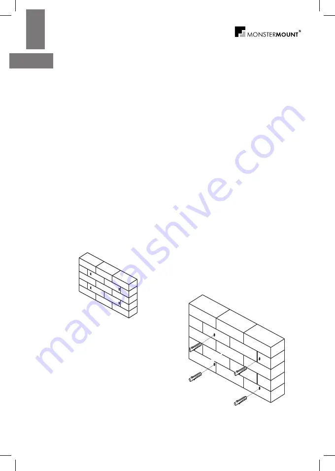
2. While another person holds the wall plate in place, mark four locations on the 
wall for securing the mount (see Fig. 3).

3. Set the wall plate aside and drill a 10 mm (3/8”) hole at each marked loca-
tion.  Remove any excess dust from the holes.

4. Insert a concrete anchor (C) into each hole so that it is flush with the concrete 
surface (see Fig. 4). A hammer can be used to lightly tap the anchors into place 
if necessary.

NOTE:

 If the concrete wall is covered by a layer of plaster or drywall, the con-

crete anchor must pass completely through the layer to rest flush with the  
concrete surface.

5. Place the wall plate back against the wall and attach it using the M8 x 63 
screws (A) and M8 washers (B) provided (see Fig. 2). 

Do not over-tighten 

these bolts and do not release the wall plate until all bolts are in place. 

Ensure that the wall plate remains level after all bolts are secured.

STEP 1B

Fig. 3

Fig. 4

Summary of Contents for MB-3105

Page 1: ...MB 3105 Installation instructions Руководство пользователя Flat Panel Wall Mount Кронштейн для крепления плазменной панели LCD ...

Page 2: ...ce 2 The wall or mounting surface must be capable of supporting the combined weight of the mount and the display otherwise the structure must be rein forced Maximum allowed screen size is 60 152 cm Maximum allowed weight of the display is 75 kgs Maximum allowed mounting pattern 800 x 500 mm 3 Safety gear and proper tools must be used Failure to do so can result in property damage and or serious in...

Page 3: ...ting the wood during installation 2 With the help of another person place the mount against the wall and level it using the integrated bubble level 3 While another person holds the wall plate in position mark four locations two per stud for securing the mount to the wall see Fig 1 4 Set the wall plate aside and drill a 6 mm 1 4 pilot hole at each marked location 5 Place the wall plate back against...

Page 4: ...t each marked loca tion Remove any excess dust from the holes 4 Insert a concrete anchor C into each hole so that it is flush with the concrete surface see Fig 4 A hammer can be used to lightly tap the anchors into place if necessary NOTE If the concrete wall is covered by a layer of plaster or drywall the con crete anchor must pass completely through the layer to rest flush with the concrete surf...

Page 5: ...if the mounting holes are recessed you will need to use the longer screws E or G and may also need to use the spacers I 2 Determine the correct diameter of screw to use by carefully trying one of each size M6 and M8 from the hardware kit Do not force any of the screws if you feel resistance stop immediately and try a smaller diameter screw 3 Insert the tilt adjustment rod so that it passes through...

Page 6: ...M6 washers H M8 screws do not require washers b If you are using the longer screws on a display with a curved or recessed back you may also need to use the spacers I Use one spacer or two spac ers stacked as needed Only use a spacer if necessary 7 Close the mount arms by returning them to the original position Insert the pin and replace the clip on both arms Make sure the tilt adjustment rod is tu...

Page 7: ...to prevent the display from being accidentally knocked from the mount OPERATION AND ADJUSTMENT 1 To change the tilt angle of your display hold the display firmly with one hand and rotate one of the tilt adjustment knobs towards the display away from the wall to unlock the tilt Make sure you rotate the knob fully Carefully move the display to the desired position and then return the tilt adjustment...

Page 8: ...e made only upon purchase receipt presentation 3 Warranty is not valid in case of the unit was assembled not in accordance with installation instructions repair or modification was done by companies without Monster Mount authorization defect appeared due to fire flood lightning deforming cleaning extremely high temperature solvent acids wrong use or careless terms the products have been lost damag...

Page 9: ...Максимально допустимый размер крепежа дисплея 800 x 500 мм 3 Необходимо использовать предохранительный механизм и соответ ствующие инструменты Несоблюдение этих требований может привести к повреждению оборудования и или серьезному травмированию людей 4 Для выполнения монтажа требуется как минимум два человека Ни в коем случае не пытайтесь выполнять монтаж в одиночку 5 Соблюдайте все указания и рек...

Page 10: ... по пузырьку воздуха встроенного уровня аккуратно выровняйте настенную часть кронштейна 3 Пока Ваш помощник удерживает кронштейн в нужном положении поставьте на стене четыре по две на каждой стойке метки по установоч ным отверстиям настенной пластины кронштейна Убедитесь что метки расположены по центру стоек 4 Отложите настенную часть кронштейна в сторону и по установленным мет кам просверлите в с...

Page 11: ...ий 4 Вставьте по одному по одному дюбелю С в каждое отверстие рис 4 По мере необходимости можно использовать молоток для более легкого втапливания дюбелей в отверстия Примечание Если бетонная стена покрыта слоем штукатурки или гипсо картона то дюбель необходимо протолкнуть глубже покрывающего слоя вровень с поверхностью железобетонной стены 5 Вдвоем приложите подставку к стене и зафиксируйте ее ис...

Page 12: ...ы E или G и втулки I 2 Определите правильный диаметр болта пробуя каждый болт из пози ций M6 и M8 комплекта крепежных деталей Не прилагайте чрезмер ных усилий при использовании болтов если чувствуете некоторое сопротивление во избежание повреждений дисплея 3 Протяните регулировочную планку между двумя кронштейнами как показано на иллюстрации рис 5 Присоедините рукоятки J с помощью болтов M4 х 10 K...

Page 13: ...те болты M6 Вам также понадобятся шайбы M6 H Для болтов M8 шайбы не нужны b если Вы используете удлиненные болты для дисплеев в с изогнутой или утопленной задней панелью Вам могут понадобится втулки I Но не используйте их без необходимости 7 Закройте кронштейны вернув их в изначальное положение Вставьте заглушки и верните рукоятки на оба кронштейна Убедитесь что регули ровочная планка закрыта пове...

Page 14: ...штейна ВАЖНО Рычаги безопасности должны быть задействованы всегда во избежание случайного падения дисплея Использование и регулировка 1 Для того чтобы изменить угол наклона дисплея придерживая дисплей одной рукой поверните один из рычагов по направлению к дисплею от стены Убедитесь что Вы полностью открутили рычаг Аккуратно переведите дисплей в выбранную позицию а затем верните рычаг в изна чально...

Page 15: ...а подтверждающего факт продажи 3 Гарантия не действует если изделие использовалось или устанавливалось с отступ лениями от инструкции по установке и эксплуатации если в ремонте или модификации изделия участвовали фирмы не имеющие соответствующей авторизации произво дителя если недостаток возник вследствие чрезвычайных обстоя тельств как то пожар наводнение удар молнии деформи рующая чистка воздейс...

Page 16: ...MB 3105 ...

Reviews: