background image

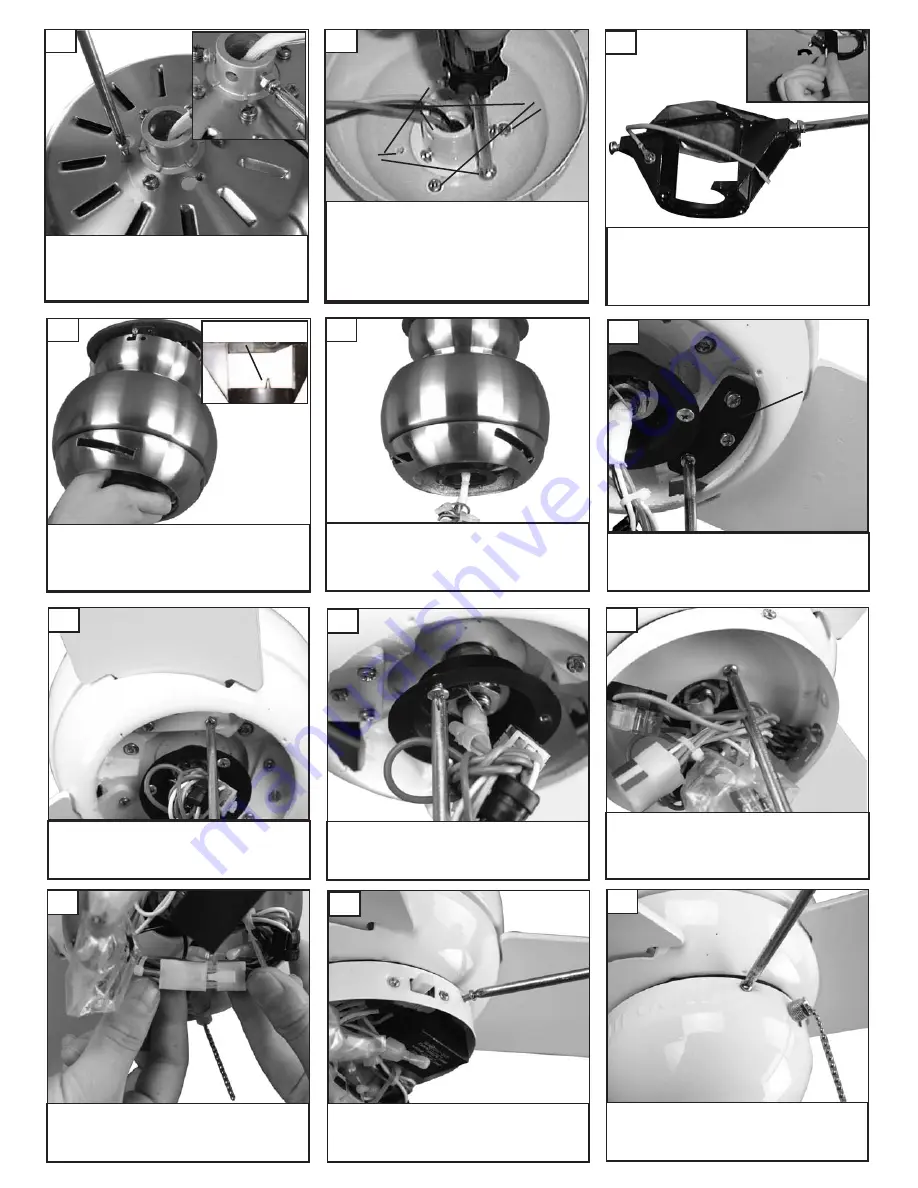
Install blades and blade plates to

motor using the 9 motor screws pro-

vided.  Tighten screws securely.

25

Install two screws corresponding with the

“L” shaped holes in the canopy only part

way so that canopy can twist into place.

Remove the all thread studs from the

lower part of the mounting bracket.

Lift fan to mounting bracket, aligning the “L”

shape holes with the scresws on the mount-

ing bracket.  Turn the fan  clockwise to lock

in position. Install the other two screws and

tighten securely.

21

23

Hang fan from mounting bracket by

the hands free hook into a closed

hole on the edge of the Canopy.

Note: For Canadian mounting refer to

Step #10.

Place canopy on top of the fan motor allowing the

yoke, wires and safety cable to pass through the

large hole in the center of the canopy.  Align the 3

larger holes around the center hole with the 3

screws still installed in the fan.  Install 3 screws

removed into small holes in canopy to make it a

flush mount canopy and tighten screws securely.

20

22

Canopy

Center

Hole

Larger

holes

Smaller

holes

Hands free hook

Loosen 2 screws with key slots and

remove 1 screw without slot from

motor plate and save screw. 

26

Install switch housing plate by twist-

ing plate with key hole slots into

place. Replace screw removed and

tighten the 3 screws securely. 

27

Connect plug from fan to switch

house plug. 

28

Remove 3 screws and save to install

switch housing. 

Install the switch housing using the

3 screws previously removed.

30

29

Align the blade and then the blade

plate with castings on motor to

attach blades to motor. 

24

Blade plate

Remove 2 screws in yoke (see

insert). Remove 3 screws with key-

hole slots from top of fan.

19

Summary of Contents for 3TF24XX Series

Page 1: ...QUALITY CEILING FANS Ceiling Fan Installation Instructions For 3TF24XX Series Fans READ AND SAVE THESE INSTRUCTIONS Total fan weight OWNER S MANUAL ...

Page 2: ... place a switch where it can be reached from a tub or shower The combustion airflow needed for safe operation of fuel burning equipment may be affected by this unit s operation Follow the heat ing equipment manufacturer s guideline safety standards such as those published by the National Fire Protection Association NFPA and the American Society for Heating Refrigeration and Air Conditioning Engine...

Page 3: ...iliments are outside of the wirenut After making the wire connections the wires should be spread apart with the grounded con ductor and the equipment grounding conductor on one side of the outlet box and ungrounded conductor on the other side of the outlet box 14 Connect black and blue wire from fan to Black or Hot wire from house Connect White wire from Fan to White Neutral wire from house Connec...

Page 4: ... through the large hole in the center of the canopy Align the 3 larger holes around the center hole with the 3 screws still installed in the fan Install 3 screws removed into small holes in canopy to make it a flush mount canopy and tighten screws securely 20 22 Canopy Center Hole Larger holes Smaller holes Hands free hook Loosen 2 screws with key slots and remove 1 screw without slot from motor p...

Page 5: ...n the ceiling above the tip of one of the blades Measure this distance from blade tip to ceilng Keeping measure within 1 8 rotate the fan until the next blade is positioned for measure ment Repeat for each blade If all blade levels are not equal you can adjust blade levels by the fol lowing procedure To adjust a blade tip down insert a washer not supplied between the blade and blade holder at the ...

Reviews: