background image

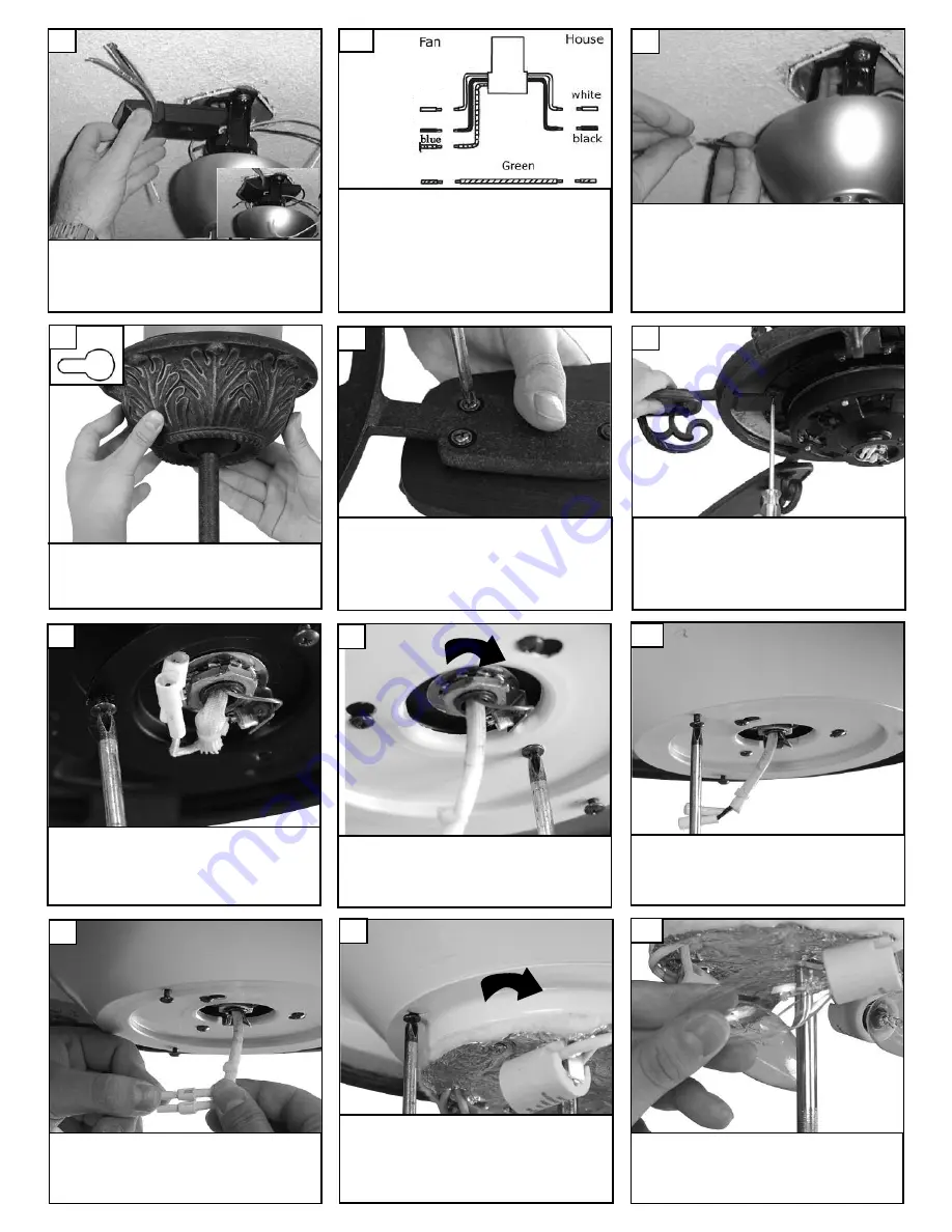
Install remote receiver by sliding into opening in

the Mounting bracket.  Make sure that the dip

switches on the Transmitter and the Receiver

are set to the same position.  See page 7 for

remote operation.

31

Make wire connections to power source using

wire nuts provided.  Make sure that no filiments

are outside of the wirenut. After making the

wire connections, the wires should be spread

apart with the grounded conductor and the

equipment-grounding conductor on one side of

the outlet box and ungrounded conductor on

the other side of the outlet box.

33

Lift canopy to ceiling aligning the key hole slots

with the screws on the bottom of the mounting

bracket.  Rotate the canopy counter clockwise

to lock in place.  Tighten the screws to secure

the canopy.  See inset for keyhole shape

34

Make wiring connections as indicated above.

White from fan to white from remote marked

N. Blue from fan to blue from remote marked

light. Black from fan to Black from remote

marked L. White from house to white from

remote marked AC N . Black from house to

Black from remote marked AC L. Connect all

green ground wires to Ground wire from

House.

white

black

32

Check the motor for plastic shipping sta-

bilizer tabs and remove if they are pres-

ent. The screws, washers and motor pads

are pre-installed to the blade holders.

Attach blade assembly to motor and

tighten screws securely.

36

Loosen 2 screws and remove 1

screw. Save screw removed. 

37

Twist lower cover plate into place by

twisting in direction of arrow.

Replace 1 screw removed and tighten

all 3 screws securely.  

38

Check the motor for plastic shipping sta-

bilizer tabs and remove if they are pres-

ent. The screws, washers and motor pads

are pre-installed to the blade holders.

Attach blade assembly to motor and

tighten screws securely.

35

Loosen 3 screws on light plate as

shown.

Plug white wire from fan to white

wire from light kit. Then plug black

wire from fan to black wire from light

kit.

39

40

Place light kit over screws and twist

direction of arrow into place. Then

tighten all 3 screws securely.

41

Install 3 x 40 watt incandescent can-

delabra bulbs. Bulbs included.   

42

Summary of Contents for 5CSR60AGD Series

Page 1: ...Owner s Manual Ceiling Fan Installation Instructions For 5CSR60AGD Series Fans READ AND SAVE THESE INSTRUCTIONS Total fan weigh with light ...

Page 2: ...f fuel burning equipment may be affected by this unit s operation Follow the heating equipment manufacturer s guideline safety standards such as those published by the National Fire Protection Association NFPA and the American Society for Heating Refrigeration and Air Conditioning Engineers ASHRAE and the local code authorities Before servicing or cleaning unit Switch power off at Service panel an...

Page 3: ...ate with four screws to become a complete mount ing bracket 8 Loosen set screw that holds ball 11 Slide ball down and remove pin save pin for later 12 Install yoke cover over downrod onto fan body Install arch hub onto downrod 17 16 Install downrod into yoke Align hole in downrod with hole in yoke and install cross pin Install keeper into cross pin 14 Tighten 2 downrod set screws and lock nuts 15 ...

Page 4: ...p swtiches Remote Receiver Dip switches 28 Fan and light kit combinations over 35 lbs in both flush and downrod mode the safety cable must be installed into the house struc ture beams using the 3 lag screws washers and lock washers provided Make sure that when the safety cable is fully extended the lead wires are longer than the cable and no stress is placed on the lead wires 30 Safety cable insta...

Page 5: ...ote marked L White from house to white from remote marked AC N Black from house to Black from remote marked AC L Connect all green ground wires to Ground wire from House white black 32 Check the motor for plastic shipping sta bilizer tabs and remove if they are pres ent The screws washers and motor pads are pre installed to the blade holders Attach blade assembly to motor and tighten screws secure...

Page 6: ...ttery cover Install 12V battery into wall remote Duracell MN21 Eveready A23 GP 23A all 12V Attach cover of remote by plac ing over buttons and snap the battery cover in place Place face plate over battery compartment and buttons Place remote over 2 pins on front cover Attach cover of remote by placing over 4 pins and snaping into place Install wall control unit to outlet box using machine screws p...

Page 7: ...light dimmer The light will cycle from bright to dim to bright until button is released Light will maintain last setting if turned off FORWARD REVERSE Depress rev button allow a few seconds for remote to change rotation direction with fan running HIGH SPEED MEDIUM SPEED LOW SPEED FAN OFF SETTING Turns fan off only FAN REVERSE Press once to change direction of the fan Fanmust be running to reverse ...

Page 8: ...ot equal you can adjust blade levels by the following procedure To adjust a blade tip down insert a washer not supplied between the blade and blade holder at the screw closest to the motor To adjust a blade tip up insert washer not supplied between the blade and blade holder at the two screws farthest from the motor Reverse the position of the washer if blades mount from top of blade 6 If blade wo...

Page 9: ...6 21 06 REV 0 New made from 5GMR manual ...

Reviews: