background image

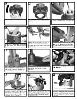
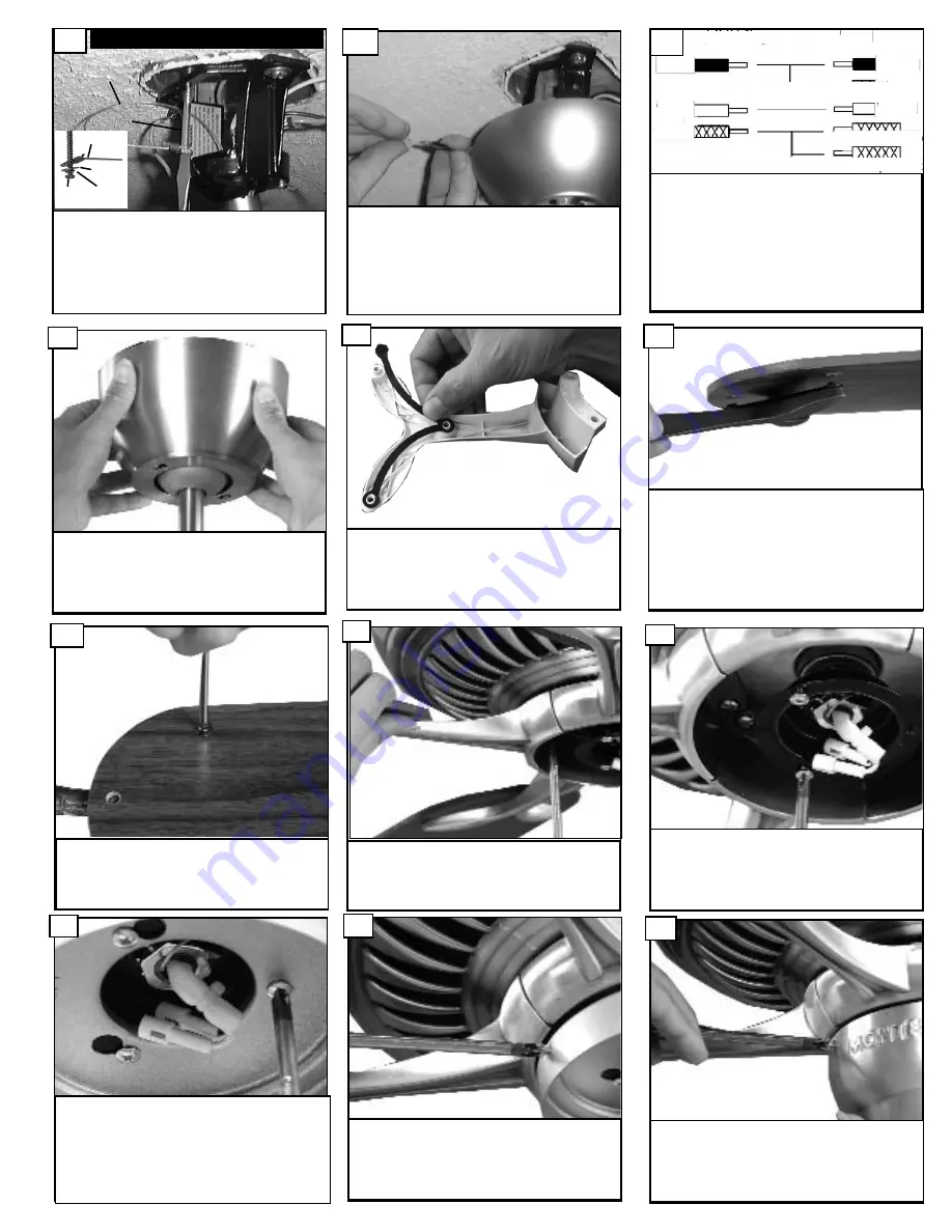
Install the switch housing using the

three screws previously removed.

30

Remove the 3 screws on the switch

housing plate and save.

29

Install the switch housing plate by

aligning the 2 screws with the 2 key

slot holes on the plate and twist to

lock into place. Install the 1 screw

removed and tighten the other 2

screws securely.

28

Loosen 2 screws and remove 1 screw

and save.

27

Attach blade assembly to motor

using the motor screws and washers

provided. Tighten screws securely.

26

Install 3 screws and washers per

blade and tighten securely.  Repeat

for all 5  blades.

25

Raise the canopy up and align the

two holes in the canopy with the two

holes in the hanger bracket. Secure

with two  screws provided.

22

Place the gasket onto the blade

bracket as shown above.

23

Warning: Only blades that come

with the fan are accepatable for

installation.

Place blade onto blade bracket with

gasket. 

24

Make sure that all exposed wiring is

secured inside wire nuts. Note: Wires

from house may vary in color and

may not include ground wire. After

wiring is conplete, gently push wires

into junction box with wire nuts

pointing upward. Refer to point 3 of

safety tips.

21

House

Fan

Black

White

Green

Black

White

Green(downrod)

Green(Bracket)

Make wire connections to power source using

wire nuts provided.  Make sure that no filiments

are outside of the wirenut. After making the

wire connections, the wires should be spread

apart with the grounded conductor and the

equipment-grounding conductor on one side of

the outlet box and ungrounded conductor on

the other side of the outlet box.

20

For Canadian installation and for USA fan and

light kit combinations over 35 lbs, in both flush

and downrod mode the safety cable must be

installed into the house structure beams using

the 3” lag screws,washers, and lock washers.

provided.  Make sure that when the safety cable

is fully extended the leadwires are longer than

the cable and no stress is placed on the lead-

wires.

19

Safety cable installation

Safety Cable

Lag Screw

safety

cable

3” lag

screw

lock

washer

washer

Summary of Contents for 5DCR60XX Series

Page 1: ...Owner s Manual Ceiling Fan Installation Instructions For 5DCR60XX Fans READ AND SAVE THESE INSTRUCTIONS Total fan weight Warning Only blades that come with the fan are accepatable for installation ...

Page 2: ... or shower The combustion airflow needed for safe operation of fuel burning equipment may be affected by this unit s operation Follow the heating equip ment manufacturer s guideline safety standards such as those published by the National Fire Protection Association NFPA and the American Society for Heating Refrigeration and Air Conditioning Engineers ASHRAE and the local code authorities Before s...

Page 3: ...ownrod into the yoke 10 Remove the keeper pin and cotter pin 9 Remove the shipping stabilizers and discard 15 Lift mounting neck to mounting Plate and align screws 7 Secure mounting neck to the mounting plate with four screws to become a complete mount ing bracket 8 17 Hang assembled fan from the mounting bracket installed to ceiling in previous step Make sure the fan is hanging straight Rotate fa...

Page 4: ...ing is secured inside wire nuts Note Wires from house may vary in color and may not include ground wire After wiring is conplete gently push wires into junction box with wire nuts pointing upward Refer to point 3 of safety tips 21 House Fan Black White Green Black White Green downrod Green Bracket Make wire connections to power source using wire nuts provided Make sure that no filiments are outsid...

Page 5: ...st speed LIGHT DIMMER To turn light on press light dimmer once quickly To turn offpress once quickly while light is on To dim light hold down button light dimmer The light will cycle from bright to dim to bright until button is released Light willmaintain last setting if turned off You can see the percentage on the dis play screen NOTE If you have more than 1 fan with a remote you will have to cha...

Page 6: ...herwise the transmitter signal will be picked up by all fans and the fans cannot be controlled separately 2 The fan can remember the running setting before power failure or cut off 3 If the new fan runs after connected to power it may be due to the fan remembering the previous running setting in the factory during the QC process push stop key on trans mitter twice to stop Operation Installation 1 ...

Page 7: ...lade tip down insert a washer not supplied between the blade and blade holder at the screw closest to the motor To adjust a blade tip up insert washer not supplied between the blade and blade holder at the two screws farthest from the motor Reverse the position of the washer if blades mount from top of blade 6 If blade wobble is still noticeable interchanging two adjacent side by side blades can r...

Reviews: