


© 2011 Monte Carlo Fan Company
2/2/2012
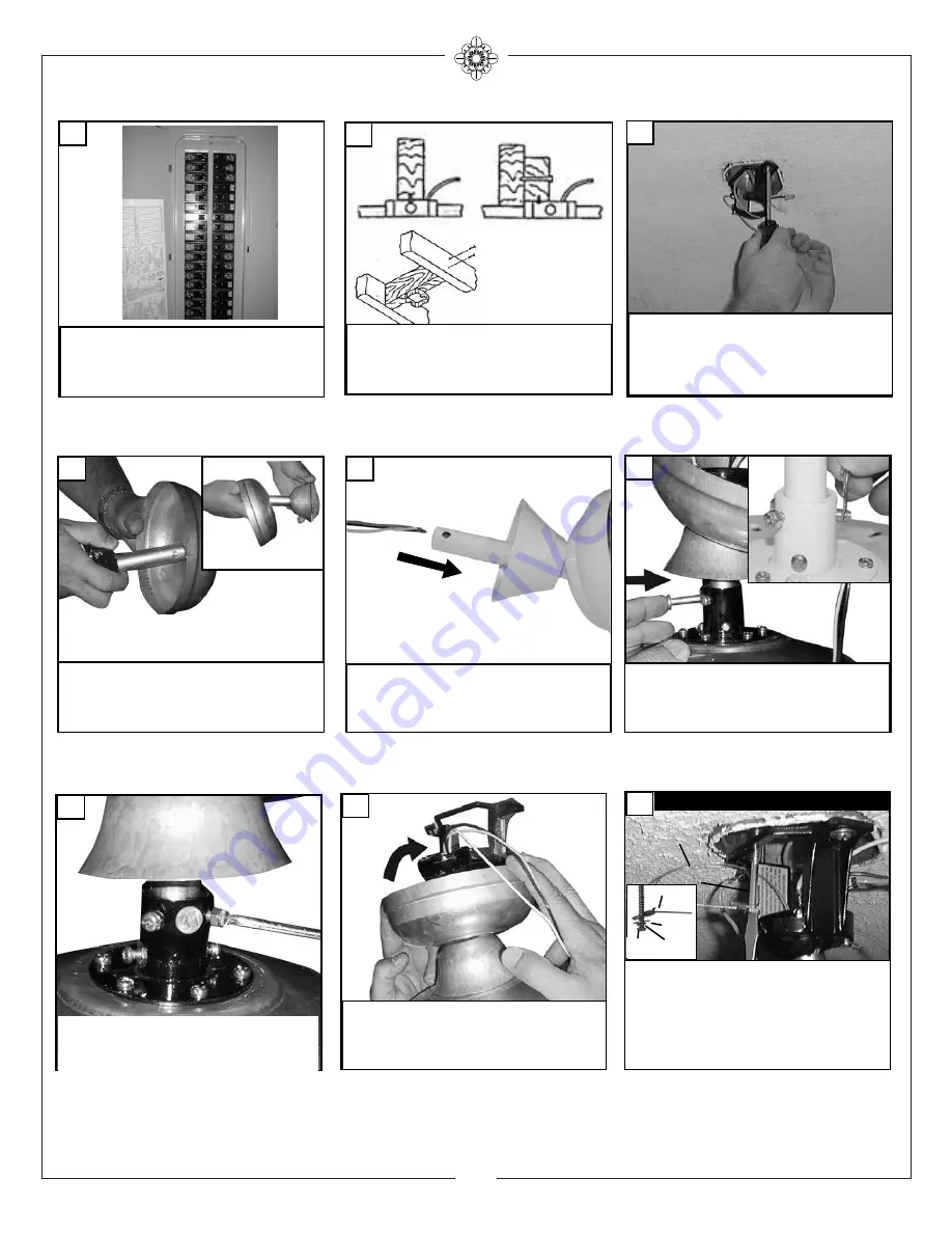
3
Insert downrod into motor yoke.
Next, insert clevis pin through yoke
and downrod and secure with cotter
pin. (see inset)
Before you begin installing the fan, Switch power off
at Service panel and lock service disconnecting means
to prevent power from being switched on accidentally.
When the service disconnecting means cannot be
locked, securely fasten a prominent warning device,
such as a tag, to the service panel.
Install canopy and yoke cover over
the downrod.
1
4
6
Thread wire through downrod with
canopy and yoke cover assembled.
5
Before installing this fan make sure the outlet
box is properly installed to the house structure.
To reduce the risk of fire, electric shock, or per-
sonal injury, mount to outlet box or supporting
system acceptable for fan support.
(Mounting must support at least 35 lbs.)
Install the Mountiing Bracket to the
Outlet box.
Use only the screws
provided with the outlet box.
3
2
Carefully lift fan assembly onto mounting
bracket. Rotate fan so that the notch on the
ball engages the ridge in the mounting bracket.
This will allow hands-free wiring.
8
7
Tighten both yoke set screws to fur-
ther secure downrod.
For Canadian installation and for USA fan and
light kit combinations over 35 lbs, in both flush
and downrod mode the safety cable must be
installed into the house structure beams using
the 3” lag screws,washers, and lock washers.
provided. Make sure that when the safety cable
is fully extended the leadwires are longer than
the cable and no stress is placed on the lead-
wires.
9
Safety cable installation
Safety Cable
Lag Screw
safety
cable
3” lag
screw
lock
washer
washer
Summary of Contents for 5GP60XX Series
Page 7: ......


