


© 2011 Monte Carlo Fan Company
2/2/2012
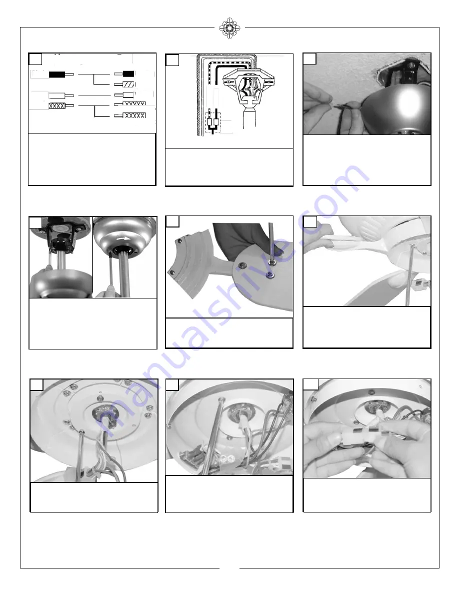
4
Loosen 2 screws with key slots and
remove 1 screw without slot from
motor plate and save screw.
16
Install 3 screws and washers per
blade and tighten securely. Repeat
for all 5 blades
14
Check the motor for plastic shipping stabilizer
tabs, and remove them if they are present. The
screws, washers, and motor pads are pre-
installed to the blade holders. Attach blade
assembly to motor and tighten screws securely.
15
Make wire connections to power source using
wire nuts provided. Make sure that no filiments
are outside of the wirenut. After making the
wire connections, the wires should be spread
apart with the grounded conductor and the
equipment-grounding conductor on one side of
the outlet box and ungrounded conductor on
the other side of the outlet box.
12
For pullchain controls, follow diagram above.
Make sure that all exposed wiring is secured
inside wire nuts. Note: Wires from house may
vary in color and may not include ground wire.
After wiring is conplete, gently push wires into
junction box with wire nuts pointing upward.
Refer to point 3 of safety tips.
10
House
Fan
Black
White
Green
Black
White
Green(downrod)
Green(Bracket)
Blue
For control of fan and optional light from wall
location, follow diagram above. NOTE: A profes-
sional electrician is recommended for this type
of installation.
11
Light
Switch
Fan Switch
Wall
Control
Install switch housing plate by twist-
ing plate with key hole slots into
place. Replace screw removed and
tighten the 3 screws securely.
17
Loosen one and remove one pre-
assembled screw from mounting
bracket. Save screw. Lift canopy up,
aligning its keyhole slot with the pre-
assembled screw on mounting
bracket and twist clockwise to lock in
place. Re-install the removed screw
and tighten all screws securely.
13
Connect plug from fan to switch
house plug. Match the color strips on
the plugs.
18
Summary of Contents for 5GP60XX Series
Page 7: ......


