


© 2013 Monte Carlo Fan Company
6/15/2013
3
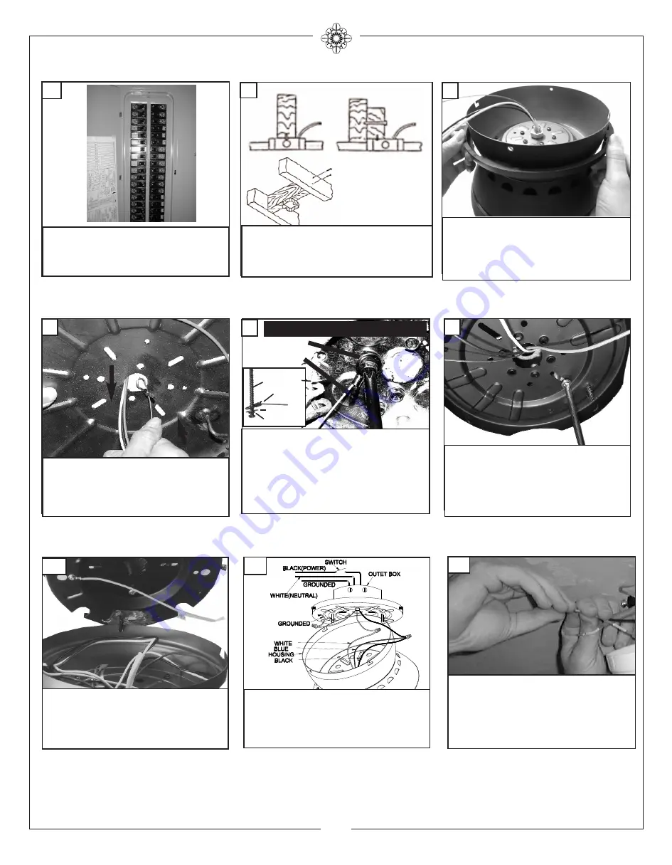
Before you begin installing the fan, Switch power off
at Service panel and lock service disconnecting
means to prevent power from being switched on ac-
cidentally. When the service disconnecting means
cannot be locked, securely fasten a prominent warn-
ing device, such as a tag, to the service panel.
1
Before installing this fan make sure the outlet
box is properly installed to the house structure.
To reduce the risk of fire, electric shock, or per-
sonal injury, mount to outlet box or supporting
system acceptable for fan support.
(Mounting must support at least 35 lbs.)
2
Thread safety cable through center
hole of the mounting plate. Thread
your house wires through center hole
also.These will be needed for wiring
of the fan.
4
Securely attached the mounting plate
to the outlet box using two screws
supplied by the outlet box.
Use
metal outlet box suitable for fan
support (must support 35 lbs).
6
Place the decorative ring on the
motor housing.
3
Make wire connections to power source using
wire nuts provided. Make sure that no filiments
are outside of the wirenut. After making the
wire connections, the wires should be spread
apart with the grounded conductor and the
equipment-grounding conductor on one side of
the outlet box and ungrounded conductor on the
other side of the outlet box.
9
Connect black and blue wire from fan to Black
or (Hot) wire from house. Connect White wire
from Fan to White (Neutral) wire from house.
Connect Ground leads from mounting bracket
and downrod to Ground lead from house.
Refer to Safety Tips section of manual.
8
Carefully lift the fan motor assembly
and engage the slot in the motor
housing with the hook on the mount-
ing plate so that the motor is se-
curely suspended.
7
For Canadian installation and for USA fan and
light kit combinations over 35 lbs, in both flush
and downrod mode the safety cable must be in-
stalled into the house structure beams using the
3” lag screws provided. Make sure that when
the safety cable is fully extended the leadwires
are longer than the cable and no stress is placed
on the leadwires.
Note
:If Installing The Second-
ary Support Safety Cable in the U.S., Do Not Re-
move Knockouts In The Outlet Box.
5
Safety cable installation
Safety Cable
Lag Screw
Lag Screw
Safety Cable
Washer
Lock Washer
Summary of Contents for TRAVERSE 5TV52 D-V1 Series
Page 7: ...Feb 2019 5TV42XXD V1 ...


