Head and Waste Containment System
Some boats are equipped with a head (marine toilet) and waste con-
tainment system. The head has either the manually operated system,
or the electrically operated system, which draws seawater in through
the hull to flush waste water from the marine toilet. The toilet pumps
the waste water on to a holding tank.
Waste Holding Tank
The boat is fitted with a waste holding tank that is emptied through
the deck plate fitting marked “WASTE.” Waste is pumped from the
head through a sanitary waste hose to the top portion of the tank. A
3/4" sanitary waste hose is attached to the bottom of the tank, and
runs to the dockside pumpout plate. An overboard vent keeps the
tank at atmospheric pressure regardless of waste levels.
All the components which comprise the waste system are made of
materials specially formulated to prevent odor permeation and to
resist chemical actions. It is strongly recommended that you regular-
ly add chemical to your tank by flushing it through the head. The
chemical helps to control odor and break down the waste. Follow the
manufacturer’s instructions on the chemical before using.
Depending on the model, there are 3 basic waste system configura-
tions; dockside pumpout, pumpout and overboard discharge, and
pumpout, discharge and macerator.
Do not flush into a full holding tank. Attempting to flush
the head when the tank is full could result in damage to
the waste system.
A waste tank indicator may be installed to provide a visual indication
of the amount of waste in the tank.
Waste Disposal
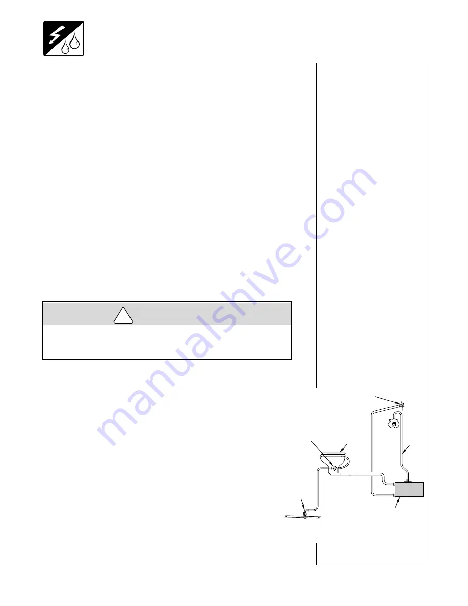
DOCKSIDE PUMPOUT
This system directs all waste to the holding tank. To clear
the tank of waste water, you will need to use the dockside
pumpout services provided at marinas, etc.
To empty the tank of waste, hook a suction hose to the
pumpout plate and to the dockside pump. The marina will
handle the proper disposal of the waste and may charge
for this service.
!
CAUTION
KC-2044
SEACOCK
TYPICAL DOCK PUMPOUT SYSTEM
HOLDING
TANK
WASTE DOCKSIDE
PUMPOUT FITTING
VENT
HEAD
MANUAL
HAND PUMP
SHIP SYSTEMS
11-14
Summary of Contents for 268 SC Sport Cruiser
Page 4: ......
Page 15: ...M 11 VECTOR SERIES AIR CONDITIONER SELF CONTAINED UNIT WIRING DIAGRAM...
Page 29: ...M 25 Use ATC series fuses 268 Bowrider and Cuddy Starboard Switch Panel Wiring Diagram...
Page 30: ...M 26 268 Bowrider and Cuddy Ignition Panel Wiring Diagram...
Page 31: ...M 27 268 Bowrider and Cuddy Instrument Panel Wiring Diagram...
Page 32: ...M 28 268 Bowrider and Cuddy DC Wiring Diagram Main...
Page 33: ...M 29 298 Bowrider AC Wiring Diagram Main 1 of 3...
Page 35: ...M 31 298 Bowrider Water System...
Page 36: ...M 32 298 Cuddy DC Wiring Diagram Main 1 of 5...
Page 37: ...M 33 298 Bowrider DC Wiring Diagram Main 2 of 5...
Page 78: ...OPERATION 4 10...
Page 90: ...6 RUNNING 6 8...
Page 106: ...STORAGE 9 4...
Page 130: ...SHIP SYSTEMS 11 18...


