XG0222
36
Installation
Control Board upgrade/replace
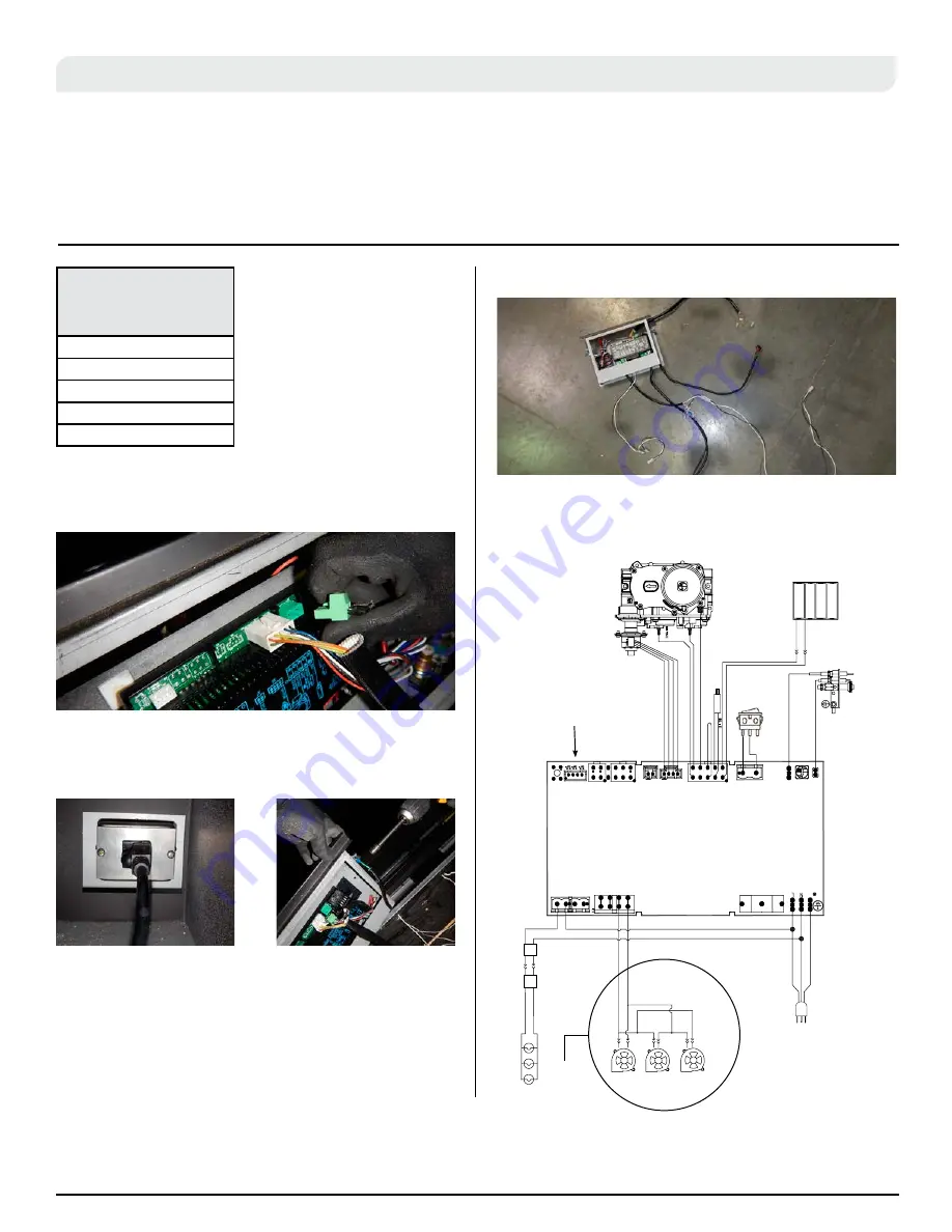
1. Remove existing basic board drawer by unplugging all existing
connections.
When upgrading the
Distinction control board,
the board will be shipped
with the board installed in
the drawer and with the
appropriate cables installed.
2. Unplug PPO from board located underneath the pilot
assembly. Disconnect the ground and remove drawer
completely.
3. Discard old drawer and wall switch and valve wires.
4. New Board.
On/Off
Switch
PPO &
Ground
Fans
LED
Pilot
Distinction (N/L) I-2 Wiring Diagram
1.5V AA type
1.5V AA type
1.5V AA type
1.5V AA type
WHIT
E
BLAC
K
BLAC
K
WHITE
GREEN
Lights
ON/OFF
CONTROL
MAI
N
Power
120VAC 60 Hz
6 Amps
SPAR
K
SENSOR
RE
D
BLACK
BATTERY
PACK
MAIN ON/OFF
SWITCH
YELLOW/GREEN
PILO
T
R
ORANG
E
GREE
N
BLAC
K
BROW
N
YELLO
W
ORANG
E
6
10
6
OPTIONAL CPI/IPI SWITCH
WHITE
LED Lights
LED1 - Red LE
D
LED2
A
mber LE
D
SW
1
LED
otroe
r
LED power
spp
y
white
white
white
BLAC
K
WHIT
E
VARIABLE SPEED
COMFORT FAN
S
Multicolored
LED Lights
Fan Kit only available in
Single sided version
Optional CPI/IPI Jumper
Multicolored
LED
Controller
Multicolored
LED Power
Supply
Figure 24.
Remove existing basic board
Figure 24.b
Remove existing basic board
Figure 24.c
Proflame2 Board
Figure 24.d
Distinction (N/L) I-2 Wiring Diagram
Adding options to DL units
requires control board
upgrades for the following
options
Fan Kit
DFK-3
LED Kit
MCLEDDL**
Remote Control
Stepper Motor
Powervents

