H36PVN Power Vent Indoor Gas Fireplace
Page 17
XG0649 - 031511
Installation
Installing an In-Line Linear Power Vent (LDVPV58)
This section applies to installations where an external roof
or wall mounted power vent is not aesthetically acceptable
or feasible.
Venting Layout
Selection of components and details of venting lay out should
adhere to the following guidelines:
Ensure there is a minimum run of 2’ of straight pipe between
the fireplace and the power vent
Ensure the maximum vent run does not exceed 60'
Maximum vent run must be reduced by 10’ for 1’ of pipe
running in a vertical downward direction
Ensure the number of 90º elbows does not exceed 3 (maximum
allowable vent run must be reduced by 10’ for every additional
90º elbow added)
Ensure the number of 45º elbows does not exceed 6
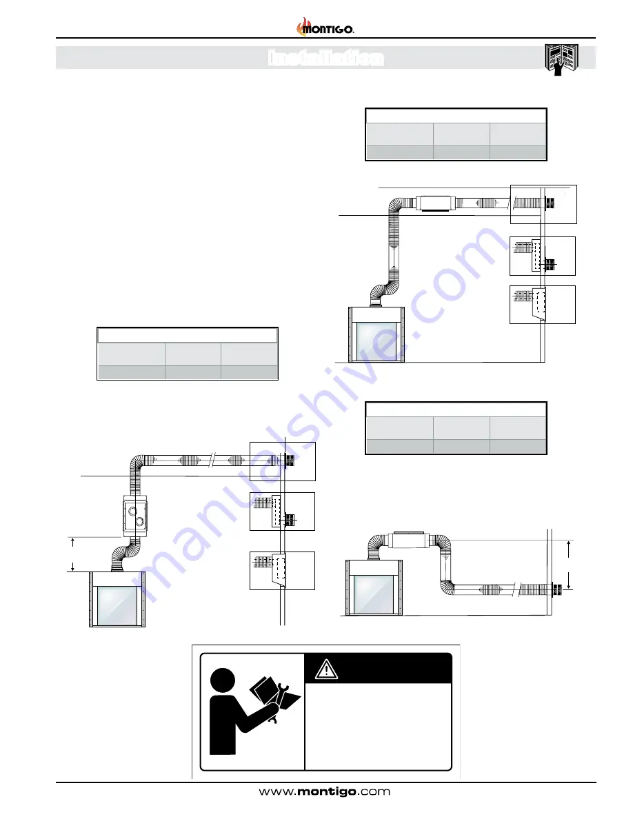
Linear Power Vent - Horizontal Termination
Example A.
Vertical mounting with horizontal termination
** from fireplace to in-line power vent
Maximum allowable vent run must be reduced by ten feet (10'-0"
for every additional 90° elbow added . With a snorkel Termination,
reduce the total vent run by an additional twenty feet (20'-0") .
Figure's
7 and 7a
.
Figure 7.
Vertical Mounting for the Linear Power Venter
Figure 7a. Horizontal Vent for the Linear Power Venter.
Example B.
Horizontal mounting with horizontal termination
** from fireplace to in-line power vent
Example C.
Horizontal mounting with downward vent run and
horizontal termination
** from fireplace to in-line power vent
Maximum allowable vent run must be reduced by ten feet (10'-0")
for every additional 90° elbow added . Also, deduct ten feet (10'-0")
of vent length for every one foot (1'-0") of vent run traveling in a
downward direction .
Figure 7b.
HorizontaI Linear Power Vent with Downward vent
and Horizontal Vent Run to Termination.
CAUTION!
Vent terminations can be very hot. The termination is to be installed higher than 7 feet above a public walkway.
Do not obstruct, or attempt to conceal, the vent termination. These actions will affect the operation of the fireplace, and may be hazardous.
In heavy snow areas, take extra care to prevent snow buildup from obstructing the vent termination.
■ Vent terminations can be very hot. The
termination is to be installed higher than 7 feet
above a public walkway.
■ Do not obstruct, or attempt to conceal, the vent
termination. These actions will affect the operation
of the fireplace, and may be hazardous.
■ In heavy snow areas, take extra care to
prevent snow buildup from obstructing the vent
termination.
CAUTION
XW2026
Venting Installation
Maximum
Vent Run
Minimum
Vent Run**
Max. #
Elbows
60 Feet
2 Feet
3
Venting Installation
Maximum
Vent Run
Minimum
Vent Run**
Max. #
Elbows
60 Feet
20 Feet
3
Venting Installation
Maximum
Vent Run
Minimum
Vent Run**
Max. #
Elbows
40 Feet
2 Feet
3
2’-0 ”
MIN
Vertical Installed
Linear Power Vent
Horizontal Run Flex Pipe
Vertical
Flex Pipe
90deg
Elbow
90deg
Elbow
90deg
Elbow
Termination
Snorkel
Termination
LDVPV58
Flush
Termination
VLWB-8
Option
Option
LDVPV58
Horizonta
l
Insta
ll
e
d
Linear Power Vent
Horizontal Run Flex Pipe
Vertical
Flex Pipe
90deg
Elbow
90deg
Elbow
90deg
Elbow
Termination
Snorkel
Termination
Flush
Termination
VLWB-8
Option
Option
Horizontal Installed
Linear Power Vent
Horizontal Run Flex Pipe
Vertical
Flex Pipe
90deg
Elbow
90deg
Elbow
Termination
6’-0”
Max.
LDVPV58


