background image

H*42DF Indoor Gas Fireplace

Page 10

XG0148 - 151123

Installation

Section: 

Section 3-2:

  Installing a Roof Mounted Termination (PVTK-1)

This section applies to installations where the direct vent termi-

nation will be roof mounted.

Section 3-2-1:


 Venting Layout

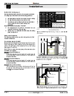
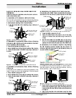
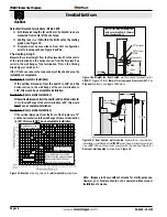
Selection of components and details of venting lay out should 

adhere to the following guidelines:


„

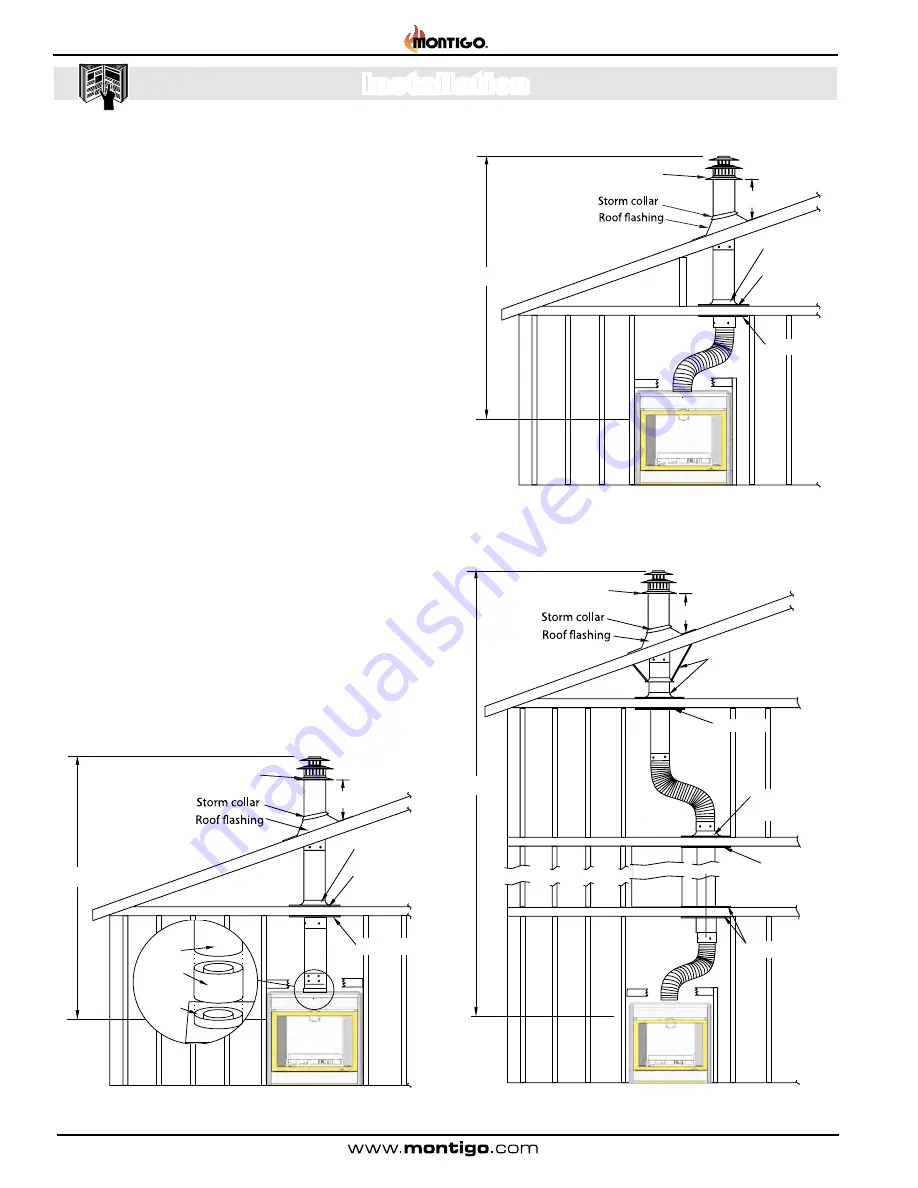
The maximum termination point is 32’ above the fireplace 

(NOTE: if the maximum termination height is used, the flame 

pattern may be affected).


„

The Vertical termination must be a minimum 2’ higher than 

where the termination exits the roofing materials, (asphalt 

shingles, cedar shakes, etc). This distance should be 

measured from the high side of the roof slope where the 

flue flashing intersects the roofing materials. (see Figures 

10 to 10c ).


„

Termination location must be a minimum 6’ from a mechanical 

air inlet.


„

For a more detailed diagram of allowed termination locations, 

see Appendix A.


„

A maximum of two offsets (each offset is made up of 2-90° 

bends) may be made for vertical vent runs.


„

Firestops must be installed as required by National & local 

codes.


„

Ensure all horizontal runs are supported with a minimum 

of 3 supports per 10’ of venting.


„

Install all roof flashing and storm collars as shown.

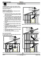
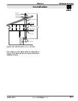
Figure 10.


Top vent, Roof mounted

  termination with no offset in vent run.

Figure 10a.


Top vent, Roof mounted 

with 1 offset (1 offset= two 

90° bends).

Figure 10b.


Top vent, Roof mounted 

 with 2 offsets (1 offset= two 

90° 

bends).

Roof mounted Terminations

The following details are some possible configurations for Roof 

mounted terminations. See below.

Support ring

Support plate

Firestop

32’ max.

2’ min.

PVTK1 

Termination

Support ring

Support plate

Firestop

32’ max.

2’ min.

Obstacle

PVTK1 

Termination

PEXT

PEXT-10
   Adaptor

Flue
Collar

Support straps 

or


support plate  & ring

2’ min.

Firestop

Firestop


Firestop

32’ max

Support plate  

& ring

Obstacle

PVTK1 

Termination

Summary of Contents for H42-DF

Page 1: ...igh voltage Toxic Flammable materials Corrosive Fork lift trucks Danger overhead crane Explosion risk Oxidising Danger of death Biohazard Laser Radiation Danger of entrapment Hot surface General Warni...

Page 2: ...tallation only available for SIT Electronic Ignition Systems 21 Section 5 1 FUEL CONVERSION 22 Section 5 2 GAS PRESSURE 22 Section 5 3 GAS CONNECTION 22 Section 6 Finishing 23 Section 7 Screen Install...

Page 3: ...he following table Refer to your rating plate to verify included options Throughout this manual instructions are applicable to all models designated as H 42DF unless otherwise noted Warranty Informati...

Page 4: ...A C22 1 1 Installations in the USA must conform to the local codes or in the absence of local codes to the current version of National Fuel Gas Code ANSI Z223 1 NFPA 54 Electrical Installations must c...

Page 5: ...ion Section Rating Plate Sample LB1223 V5 1 SIT IPI with screen DEC06 2014 Teklynx LabelView Demo Figure A Rating Plate for IPI eletronic ignition Figure B Rating Plate for standing pilot SIT LBL1205...

Page 6: ...nces to air conditioning ducts electrical wiring and plumbing Safety as well as efficiency of operation should be consideredwhenselectingthefireplacelocation Selectalocation that does not interfere wi...

Page 7: ...oor opening 3 Rear Vent Ceiling level Floor Top Vent 18 max Min 1 Non Combustible Header Non Combustible materials Alcove over fireplace 33 Exterior Wall Non Combustible Nailing Flange supplied figure...

Page 8: ...ler to discuss power venting options NOTES FOR PLANNING VENTING Venting originates from the unit through the top or through the rear Venting can terminate through the roof or through an exterior wall...

Page 9: ...shing around the fireplace MODEL Top Rear Vent Top Top Vent Back Sides Floor Mantel 6 Figure 7 Installing the Nailing Flange Extension Installing The Standoffs To avoid elevated mantel temperatures al...

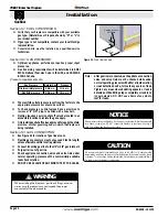
Page 10: ...mamechanical air inlet Foramoredetaileddiagramofallowedterminationlocations see Appendix A A maximum of two offsets each offset is made up of 2 90 bends may be made for vertical vent runs Firestops mu...

Page 11: ...Section Figure 10c Rear vent Roof mounted venting 1 90 bend Support ring Support plate 32 max PVTK1 Termination 18 Max Note Images are shown without screens for clarity purposes However your fireplace...
Page 12: ...on Selection of components and details of venting layout should adhere to the following guidelines Vent terminations must not be recessed in walls or siding For Heat Shield requirements see Section 3...

Page 13: ...ame the BSR opening to 12 x 12 2 Secure the BSR Frame to the exterior sheathing of the structure 3 Fasten the termination to the BSR Frame using a minimum of 4 screws 1 Frame the MOSR opening to 12 x...

Page 14: ...120 Max Figure13c Top Vented wall mounted Retracted Multi elbow installation See Venting Graph for Top vent wall mounted terminations Figure 13 Note Images are shown without screens for clarity purpo...

Page 15: ...ch to the termination 45 or less Corner Installation Use an PTO 3 termination and an PFL 1 or PFL 2 PFL 2 12 or 24 compressed length and a frame if appropriate Flex may be turned to obtain desired deg...

Page 16: ...flange of the vent termination is 96 this would NOT be an acceptable installation Example C Unacceptable Installation If the vertical dimension from the floor of the fireplace is 72 andthehorizontalru...

Page 17: ...to consult your Building Envelope Engineer or Waterproofing Consultant for further recommendations Section 3 3 2 Venting Components The following components and associated Montigo part num bers for in...

Page 18: ...1 Min 1 Min Combustible Framing RHS8 Heat Shield 36 Min 60 Min Termination Drywall sheetrock RHS101 Heat Shield inner Section RHS101 Heat Shield Outer Section Combustible framing Termination Drywall...

Page 19: ...d Screw Wall Switch Fan Plug Receptacle Manifold Pressure Test Connection Wall Switch Power Generator Pilot Adjustment Screw Inlet Pressure Hi Lo Adjustment Knob Gas Control Knob Shown in Pilot positi...

Page 20: ...nside the fireplace depending on the model of the unit Use only low voltage wire and DO NOT connect any external power to the remote switch Refer to Figure 18 19 or 20 for wiring requirements NOTE The...

Page 21: ...a second or third time depending on prevailing temperatures or altitude When in CPI mode the pilot also keeps the system warm During a cold start condensation will normally form on the inner glass sur...

Page 22: ...ve and valve train under normal operating pressure with a commercially available leak check solution DO NOT USEAFLAME OFANYKIND TO TEST FOR LEAKS Section 5 1 FUEL CONVERSION Verify that your fireplace...

Page 23: ...lace may be hot to touch We recommend careful consideration be given to the effects of elevated mantel temperatures which may be in excess of product design for example candles plastic or pictures Thi...

Page 24: ...en Tab Receptacles in the lower section of the fireplace Makesurethetabsandscreensareloweredallthewaydown intotheScreenTabReceptaclesonthefireplace Then push each Upper Screen Stud on the top corners...

Page 25: ...e tool is firmly in the lower end of the slot as shown Then pull toward you Caution hold the tool securely 3 Step 6 Pull hard if necessary to release the spring ten sion Caution The latch springs back...

Page 26: ...Door Step 8 GrasptheDooroneitherside usuallymidwayandliftupward liftthedoorcarefullyupandawayfromthefrontofthefireplace See Figure 26g Place the Door aside in a safe place whilemaintenanceand orclean...

Page 27: ...gs using the predetermined alignment holes cast into the underside of the logs as shown above figure 27c Step 2 Place the bottom Rear log as shown in figure 27 Figure 27 Placing Bottom Rear Log Step 1...

Page 28: ...ed Rocks The HL42DF has the option of installing the cultured rocks which mimic real stone These may be spaced at random or in a visual pattern of your preference in the burner pan See the Montigo web...

Page 29: ...Rock Guard should line up between the air inlets of the burner Figure 29d Pushing the Rock Guard down into place Rock Tray Front Cover Figure 29f Completed Placement of Rock Guards Installing the Des...

Page 30: ...nt 3 faux ceramic rock E as shown 6 Place 11 eleven faux rocks F as shown below Figure 30g Placement 11 faux ceramic rock F as shown Figure 30h Completed Placement Note You may have to adjust the Faux...

Page 31: ...shown in figure 30c Place Log C knot hole as shown Figure 31d Place log D and then E note placement of Knot on log Log E 4 Place the Long front Left log Log D as shown in figure 30d Angle log with kn...

Page 32: ...remote switch to ignite fire NOTE Gas control knob cannot be turned from PILOT to OFF unless knob is pushed in slightly Do not force with American Flame Electronic Ignition For Your Safety READ BEFORE...

Page 33: ...s go to the next step 6 Turn fireplace ON using wall switch or remote control 7 If the Fireplace does not light the System will cycle through two trials one minute audible clicking thirty seconds of s...

Page 34: ...the safety information above on this label If you don t smell gas go to the next step 5 Turn switch on the gas control to ON NOTE This unit is equipped with an ignition system that lights the pilot b...

Page 35: ...e Key is provided to index between the features and a Thermostat Key is used to turn On Off or index through Thermostat functions see Figure 32 Additionally a Key Lock feature is provided The Proflame...

Page 36: ...ook at the LCD screen on the Remote Control to verify that a C or F is visible to the right of the Room Temperature display Turn On the Fireplace With the system Off turn the master override switch to...

Page 37: ...the remote control will change to show that the room thermostat is On and the set temperature is now displayed To adjust the set temperature press the Up or Down Arrow Keys until the desired set temp...

Page 38: ...his function use the Mode Key see Figure 32 to index to the accent light icon see Figure 45 Pressing the Up Arrow Key will turn the light on at the lowest setting Continue pressing up to get brighter...

Page 39: ...eys at the same time see Figure 47 To de activate this function press the Mode and Up Keys at the same time Remote Control When the Remote Control batteries are low a Battery Icon will appear on the L...

Page 40: ...he door as shown on Page 25 Handle the door carefully and clean it with non abrasive glass cleaners One of the most effective products is Kel Kem Silicone seals on inner door during initial firing wil...

Page 41: ...will not Light 1 Check and verify all wiring connections as per the wiring diagram 2 Verify the inlet and Manifold Pressurearewithinacceptablelimits Pilot lights but Main burner will not Light and ig...

Page 42: ...RPG001 Piezo Ignitor PIEZO Pilot Tubing RPTA03 Door RDTH42 Replacement Screen RSCH42 SIT IPI Proflame 2 Replacement Parts List HR42DF H42DF HL42DF Log Set N A RLGSH42 N A NG Gas Valve Hi Low RGC3044 L...

Page 43: ...iance 100 000 BTU H 30 KW 12 inches 12 inches M clearance to forced air supply inlet 6 feet 3 feet above air inlet N clearance above paved sidewalk or paved driveway located on public property 7 feet...

Page 44: ...e must be subjected to normal use The Gas Appliances are designed to burn gas only Burning conventional fireplace fuels such as wood coal or any other solid fuel will cause damage to the Gas Appliance...

Page 45: ...eight of eight 8 feet above grade directly in line with the exhaust vent terminal for the horizontally vented gas fueled heating appliance or equipment The sign shall read in print size no less than o...

Page 46: ...XG0148 151123 H42DF Residential Gas Fireplace...

Reviews: