background image

Page 16

H52-DF Gas Fireplace

Part No. XG0650

Maintenance

WARNING:

Do not attempt to clean glass when hot.
Do not clean glass with abrasive materials as any glass 

etching may cause premature glass failure.

General


Have the fireplace and installation inspected yearly

. The inspection 

must include, but is not limited to, the following: 

• 

  A visual check of the entire vent system and termination.

  An  inspection  of    the  explosion  relief  flappers  and  the  door  

gasketing to ensure a proper seal.  

  An inspection of the burner, venturi, and primary air openings.

• 

  An inspection of the gas valve, gas components, and pilot flame.  

For your convenience a 1/8" manifold pressure tap is supplied 

on the gas valve for a test gauge connection. See Figure 32.

• 

Ensure proper log placement as per this manual.

• 

Inspection of all optional equipment; fans, thermostats, etc. 

  For 

Natural Gas

 this appliance requires a minimum inlet pressure 

of 5.5" W.C. and a manifold pressure of 3.5" W.C.

  For 

Propane Gas 

this appliance requires a minimum inlet pressure 

of  11" W.C. and a manifold pressure of 10" W.C.

  Always keep the fireplace area clear and free of combustible materials, 

as well as gasoline and other flammable vapors and liquids. 

  Do not use this appliance if 

any part has been under water

. Immediately 

call a qualified service technician to inspect the appliance and to 

replace any part of the control system and any gas control which 

has been under water.

Cleaning

When the fireplace is first activated, there may be some smoking and 

a visible film may be left on the glass. This is a normal condition, and is 

the result of burning of protective coatings on new metal.

  Glass must be cleaned periodically to remove any film (which is 

a  normal  by-product  of  combustion)  which  may  be  visible.  Film 

can easily be removed by removing the door, as shown on page 

15. Handle the door carefully, and clean it with non-abrasive glass 

cleaners. One of the most effective products is Kel Kem.

  Silicone seals on inner door during initial firing will "off gas", leaving 

a visual deposit of a white substance on combustion chamber walls. 

This can easily be removed using normal household products.

  Use  a  vacuum  cleaner  or  whisk  broom  to  keep  the  control 

compartment, burner, and firebox free from dust and lint.   

  Logs may be cleaned periodically with a vacuum to remove soot or 

other contaminates.

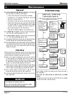
Troubleshooting 

If your fireplace still does not operate correctly, consult your dealer or 

the manufacturer.

All  service  and  repairs  should  be  performed  by  a  qualified 

agency.

All spare parts, optional fans, and optional trim finishes are available 

from your local dealer or the manufacturer.

- Tu

rn Gas Supply Of

f

- Set thermostat to

   call for heat

SV9500 / SV9600

is powered 

(24V

AC nominal

)

HSI

Terminals

NOTE:

  Before T

roubleshooting, Familiarize

 Y

ourself With 


The Startup

 A

nd Checkout Procedure.

ST

AR

T

HONEYWEL

SV9500 /9600

Tr

oublshooting Sequence

INSE

T

NO

CHECK:

- Line voltage power

- Low voltage transformer

- Limit Controller

- Thermostat

- Wirin

g

Air proving switch on 

combustion air blower system

-Vent damper (if used) is open 

and end switch made

NO

NO

YES

NO

YES

Unplug Pilot Burner Cable,

Measure V

oltage at 

SV9500/SV9600 HSI 

T

erminals (24V

AC 

Nominal, see INSET)

Replace

SV9500/

SV9600 

Igniter warms up and 

glows red.

YES

YES

NO

YES

NO

Pilot 

Valve opens.

Replace Igniter / 

Flame Rod Assembly

Replace SV9500/SV9600

NO

NO

YES

YES

Turn gas on.

Pilot Burner Lights?

Main Valve opens?

SYSTEM OK

Discard old Igniter /

Flame Rod Assembly

Measure 

Vo

lume to 

SV9500 / SV9600 Vo

ltage 

must be at least 19.5 VA

C

Check

Transformer

Line 

Vo

lt

Supply

Replace Igniter /

Flame Rod Assembly

Replace

SV9500 /

SV9600.

Save old 

Igniter/ Flame

Rod Assembly

for service.

Replace Igniter / Flame 

Rod Assembly and retain.

Restart troubleshooting

Sequence. Does main 

valve open?

Summary of Contents for H52-DFN

Page 1: ...e Safety Notice Glass doors on gas fireplaces are extremely hot while the fireplace is on and remain hot even after the fireplace has been turned off Safety screens are available and can reduce the risks of severe burns Please keep children away from the fireplace at all times C US Installer Leave this manual with the appliance Consumer Leave this man ual for future reference Check local codes and...

Page 2: ... this owner s manual unless noted other wise applies to all models and gas control systems Your new Montigo gas fireplace will give you years of durable reliable use Welcome to the FireFeature family of gas fireplace products Safety Alert Key DANGER Indicates a hazardous situation which if not avoided will result in death or serious injury WARNING Indicates a hazardous situation which if not avoid...

Page 3: ... as instructed in this manual Consult your local Gas Inspection Branch on installation requirements for factory built gas fireplaces Installation repairs should be done by a qualified contractor Installations in Canada must conform to the current CAN CGA B 149 1 and 2 Gas Installation Code and local regulations If the optional air circulating fan kit is installed it must be electrically grounded i...

Page 4: ...ir convection current on the fireplace G H J K C L I C L K J H52 Fireplace Dimensions A 52 B 56 C 47 21 2 D 373 4 E F G H 287 8 38 5 1 I 8 J N A K R H52DF 19 N A L O N M M O H52DF 29 3 4 N Framing Dimensions 52 1 4 56 1 4 B A C D D D F 12 6 1 2 G B Installing The Gas Line The gas line must be installed before finishing the H52 DFN Fireplace Natural Gas requires a minimum inlet gas supply pressure ...

Page 5: ...g the standoff s Installing The Remote Switch The H52 DFN s gas valve located behind the lower trim may be connected to a wall switch The valve generates its own power on a millivolt circuit Use only low voltage wire and DO NOT connect any external power to it Refer to Figure 15 for wiring requirements Note The switch location must not exceed 30 from the fireplace Termination Installation Thissect...

Page 6: ... LPVH60 60 foot power cord and harness LPVH70 70 foot power cord and harness LPVH80 80 foot power cord and harness Before You Begin Minimum clearances of 1 from vent to all combustible materials must be maintained The LDVPV58 must only be installed with Montigo venting components as specified in these instructions In order to maintain the power vent system integrity all 5 and 8 venting connections...

Page 7: ... Factory Installed Pipe Adapter Restrictor are not Covered when installing New Pipe Connection Venting Installation The LDVPV58 s Power Vent must be installed with the H52 DFN gas fireplaceequippedwithanelectronicignitionsystem Wheninstallingthe venting the installation must adhere to the Venting Installation Section in this Installation Operation and Maintenance Instructions as well as these few ...

Page 8: ...d by Ten feet 10 0 for every 90 elbow added Deduct ten feet 10 0 of vent length for every one foot 1 0 of vent run traveling in a downward direction Figure 7a HorizontaI Linear Power Vent with Horizontal Vent Run Linear Power Vent Vertical Vent Multi elbow installations are possible up to a maximum seventy feet 70 0 with three 3 90 elbows Minimum vent run from Fireplace to Power Vent must be two f...

Page 9: ...ure 9 LDVPV58 Power Vent overall dimensions Access Cover 18 1 2 33 1 8 11 34 7 8 Top View Side View Figure 10 LDVPV58 Power Vent framing dimensions 2 MIN 5 MIN 5 MIN 1 2 MIN Louvres Vent Framing Dimensions Figure 11 Conduit and Wiring Clearances Wiring Installation Connect the wiring to the linear power vent as outlined in the previ ous section and connect the wiring to the fireplace as outlined i...

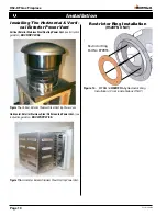
Page 10: ...11a Vertical Exterior Stainless Steel Roof top Power Vent Horizontal Exteriot Stainless Steel Wall mounted Power Vent see instruction guide for EDVWSPV47 58 Figure 11b Horizontal Exterior Stainless Steel Roof top Power Vent Installation Restrictor Ring Part No EPVR55 Figure 14 EPVR55 for H52DF Only Restrictor Ring Installation From inside firebox ONLY Restrictor Ring Installation H52DFN ONLY ...

Page 11: ... has prompted us to manufacture many models of fireplaces which are hot fuel and energy efficient Please be aware temperatures over the mantel will rise above normal room temperature and walls above fireplace may be hot to touch Warning When covering the upper metal portion of the fireplace up to 6 as shown Fig 13 Fig 14 withanon combustiblematerialPleaseNote The decorative facing materials may be...

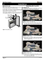
Page 12: ...t Installing the Logs TheH52 DFNissuppliedwithsevenceramicfibrelogs Unpackthelogs and handle them very carefully install as described below Figure 16 Installation of four 4 Base Logs Step 1 Place the Base Logs A B C D as shown Move them left or right to ensure they fit between the grate stiles as shown Figure 16a Installation of Log E Step 2 Place flat portion underside of Log E on the formed stee...

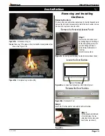
Page 13: ...e the Horizontal Access Panel Figure 28a Loccate the door buckles Both Sides Typical Step 1 Remove the Horizontal cover by placing fingers in both finger holes then pushng away from you and lifting out Place it aside during maintenance or cleaning Install in reverse order Installed Gas Valve Cover Door Latch Hook Door Latch Slot Hand hold 1 Step 3 Firmly grasp hand hold end of tool and place the m...

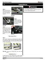
Page 14: ... 5 Pull hard if necessary to release the spring tension Caution The latch springs back with force hold the tool securely 4 Step 6 Remove the tool from the latch slot Ensure the latches are hanging freely the hook end is released from the bottom of the door Repeat all 4 steps for the remaining latches Removing the Door Figure 28d Figure 28e Figure 28f To install the door hook the top edge of the do...

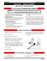
Page 15: ... to light any appliance Do not touch any electrical switch do not use any phone in your building Immediately call your gas supplier from a neighbour s phone Follow the gas supplier s instructions 1 Turn off remote switch 2 Flip down the lower trim 3 Turn the switch on the gas control to Off 4 Flip up the trim 1 STOP Read the safety information above on this label 2 Flip down the lower trims 3 Turn...

Page 16: ...oor as shown on page 15 Handle the door carefully and clean it with non abrasive glass cleaners One of the most effective products is Kel Kem Silicone seals on inner door during initial firing will off gas leaving a visual deposit of a white substance on combustion chamber walls This can easily be removed using normal household products Use a vacuum cleaner or whisk broom to keep the control compa...

Page 17: ...mal use The Gas Appliances are designed to burn gas only Burning conventional fireplace fuels such as wood coal or any other solid fuel will cause damage to the Gas Appliance will produce excessive temperatures and will result in a fire hazard Limitations On Liability It is expressly agreed and understood that The Companies sole obligation and purchaser s exclusive remedy under this Warranty under...

Page 18: ...the United States 6 feet 1 8 m minimum in Canada L clearance to non mechanical air supply inlet to building or the combustion air inlet to any other appliance 16 inches 41 cm minimum for appliances 100 000 BTU H 30kW M clearance to mechanical air supply inlet 6 feet 1 8 m minimum N clearance above paved sidewalk or a paved driveway located on public property 7 feet 2 1 m minimum P clearance under ...

Page 19: ... line with the exhaust vent terminal for the horizontally vented gas fueled heating appliance or equipment The sign shall read in print size no less than one half 1 2 inch in size GAS VENT DIRECTLY BELOW KEEP CLEAR OF ALL OBSTRUCTIONS 4 INSPECTION The state or local gas inspector of the side wall horizontally vented gas fueled equipment shall not approve the installation unless upon inspection the...

Page 20: ...Canadian Heating Products Inc Langley BC V4W 4A1 Montigo Del Ray Corp Ferndale WA 98248 XG0650 120108 ...

Reviews: