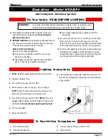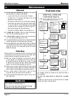
Page 4
H52-DF Gas Fireplace
Part No. XG0650
Installation
Installing The Fireplace Shell
The fireplace may be installed in any location that maintains proper clear
-
ances to air conditioning ducts, electrical wiring and plumbing. Safety,
as well as efficiency of operation, must be considered when selecting
the fireplace location. Try to select a location that does not interfere
with room traffic, has adequate ventilation, and offers an accessible
pathway for Direct Vent installation. Refer to page 4 -
Vent Installation
for more information.
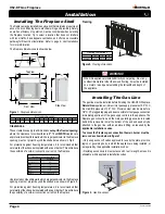
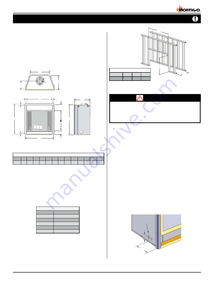
The fireplace dimensions are shown below:
Figure 2.
Framing dimensions.
Framing
Top View
Front View
Side View
Unprotected combustible walls which are perpendicular to the fireplace
opening, must not project beyond the shaded area shown in Figure 8.
For protection against freezing temperatures, it is recommended that
outer walls of the chase be insulated with a vapor barrier. This will reduce
the possibility of a cold-air convection current on the fireplace.
Figure 1.
Fireplace dimensions.
Clearances
These clearances apply to all dimensions
except the framed opening
,
where the clearance to combustibles is
0"
. The
H52DFN
clearance to
unprotected combustible walls which are perpendicular to the fireplace
opening, must not project beyond the shaded area shown in Fig. 8.
For protection against freezing temperatures, it is recommended that
outer walls of the chase be insulated with a vapor barrier. This will reduce
the possibility of a cold-air convection current on the fireplace.
G
H
J
K
CL
I
CL
K
J
H52 Fireplace Dimensions
A
52
B
56
C
47
2
1
/
2
D
37
3
/
4
E
F
G
H
28
7
/
8
38
5
1
I
8
J
N/A
K
R
H52DF
19
N/A
L
O
N
M
M
O
H52DF
29
3/4
N
Framing Dimensions
52
1/4
56
1/4
B
A
C
D
D
D
F
12”
6 1/2”
G
B
Installing The Gas Line
The gas line must be installed before finishing the H52-DFN Fireplace.
Natural Gas
requires a minimum inlet gas supply pressure of 5.5" W.C.
& a manifold pressure of 3.5" W.C. Provision must also be made for a
1/8" N.P.T. plugged tapping and be accessible for test gauge connection
immediately upstream of the gas supply controls to the appliance. The
fireplace gas connection and the main operating gas valve is located
behind the removable trim at the bottom of the unit and need only be
attached to the gas line with an approved fitting, as required by the
applicable installation codes
.
To access the fireplace gas connection the main burner must be
removed as shown below in figure 3.
• Only use gas shut-off valves approved for use by the state, province,
region, or governing body, in which the appliance is being installed, or
as required by the applicable installation codes.
• Flexible gas connectors must not exceed 3 feet in length, unless it is
allowable within applicable installation codes.
Figure 3.
Gas line access.
Gasline Acces
0.875 dia.
7
to center
2
Clearance to Combustibles
H52DFN
Top (Top Vent )
Sides
Floor
Back
36”
2”
0”
2”
Mantel
See graph, Page 9
WARNING!
When this appliance is installed directly on carpeting, tile or any
combustible material other than wood flooring, it must be installed
on a metal or wood panel extending the full width and depth of
the appliance.


