Page 5
H52-DF Gas Fireplace
Part No. XG0650
2.5”
Installation
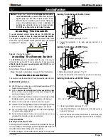
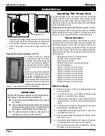
Installing Terminations with Built-In Frames
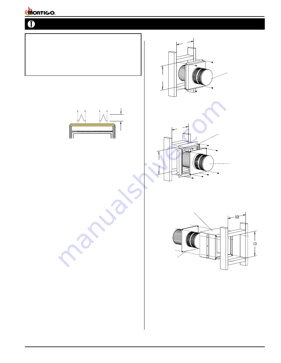
Installing Terminations with MSR Frames
12
12
1. Frame the termination opening to 12" x 12".
2. Fasten the termination to the studs using a minimum of 4 screws.
11
11
1. Frame the termination opening to 11" x 11".
2. Fasten the termination to the studs using a minimum of 4
screws.
Installing Terminations with MOSR Frames
12
12
12
MOSR
1. Frame the termination opening to 12" x 12".
2. Fasten the MOSR frame to the interior side of the studs using a
minimum of 4 screws.
3. Insert the termination into the MOSR frame as shown here, and
attach by screwing through the four pilot holes in the termination.
MSR
PTO-F (5"/8")
PTO-3F (5"/8")
PTO-F (5"/8")
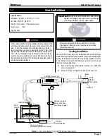
Note:
After gas line is connected,
each
appliance connection
,
valve and valve train must be checked while under normal
operating pressure with either a liquid solution, or leak
detection device, to locate any source of leak. Tighten any
areas where bubbling appears or leak is detected until
bubbling stops completely or leak is no longer detected.
DO NOT use a flame of any kind to test for leaks.
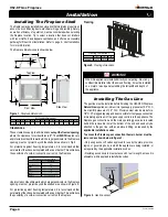
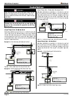
Installing The Standoffs
To avoid elevated mantel temperatures, the H52-DFN gas
fireplace is required to have the supplied standoffs installed.
The fireplace is supplied with two standoffs. Bend and install these
standoffs on top of the fireplace ensuring that the height of the standoff
maintains a 2.5" clearance.
Figure 4.
Installing the standoff's.
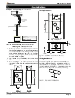
Installing The Remote Switch
The
H52-DFN'
s gas valve, located behind the lower trim, may be
connected to a wall switch. The valve generates its own power on
a
millivolt circuit. Use only low voltage wire, and DO NOT
connect
any external power to it.
Refer to Figure 15 for wiring requirements.
Note:
The switch location must not exceed 30' from the fireplace.
Termination Installation
This section covers the installation of the Various available terminations.
Installation Requirements
■
H52-DFN fireplace is certified for use with Montigo Standard Series
(5"/ 8")
flexible venting components ONLY.
■
Minimum
clearance to combustible construction around the vent pipe
is 1"
on all sides, except on horizontal venting where the
top
of the pipe
must have a clearance of at least 2".
■
Use only
certified Montigo flexible vent components.
(Use of other parts will void
the Montigo warranty, and may impede the operation of the fireplace.)
■
All joints must be secured with a minimum of two screws per joint
■
Horizontal runs must be supported by a minimum of two supports per horizontal
run. A minimum of one screw on each side of support is also required
■
Flex vent sections may be stretched up to 50% of their total length (eg. a
24" section may be stretched to 36")
■
Flexible Venting components can be used in any configuration, and in any
orientation (Male connectors can face in any direction)
Vent Terminations
Selecting A Termination Location
Choosing your vent termination location will help to determine how you
vent your fireplace. The following figures shows typical fireplace termina
-
tion installations and the venting options they provide.
For Detailed diagram of allowed termination locations, see
Appendix


