Page 9
H52-DF Gas Fireplace
Part No. XG0650
Installation
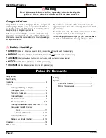
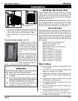
Example B.
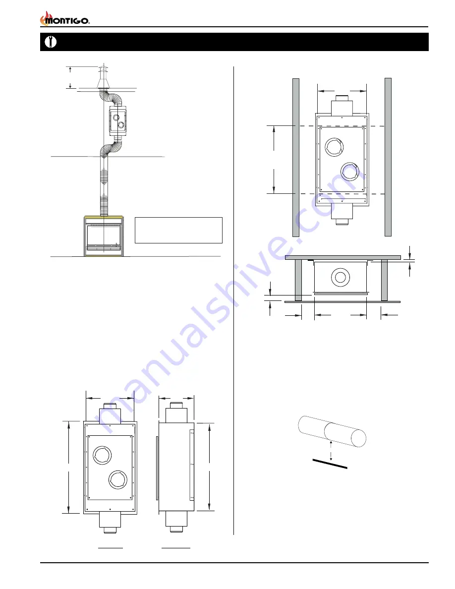
Vertical Mounting with Vertical Vent Run
Figure 8b.
VerticaI Linear Power Vent with Vertical Vent Run
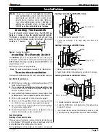
Installing the Linear Power Vent
The linear power vent can be installed to existing stud construction
1.
or directly to cement wall or roof. The LDVPV58
must maintain the
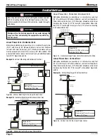
clearance to combustibles as shown in Figure 10. The required
service access panel must be framed at 28" X 18". To enclose
the service access panel, (at less than 2") a minimum 30% free
air must be supplied at all times.
Plug the power chord into the available slot in the linear power
2.
vent.
Secure all venting joints with at least three screws and ensure
3.
that the joints are properly sealed by applying high temperature
silicone.
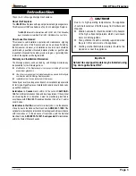
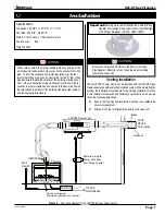
Figure 9.
LDVPV58 Power Vent overall dimensions.
Access Cover
18 1/2
33 1/8
11
34 7/8
Top View Side View
Figure 10.
LDVPV58 Power Vent framing dimensions.
2 MIN
5
MIN
5
MIN
1/2
MIN
Louvres
Vent
Framing Dimensions
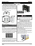
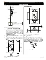
Figure 11.
Conduit and Wiring Clearances.
Wiring Installation
Connect the wiring to the linear power vent as outlined in the previ-
ous section, and connect the wiring to the fireplace as outlined in the
schematic below. Ensure that the proper clearances are maintained
for the wiring and conduit. When installing the wiring it must never run
above the vent run and it must be at least 1" clear of all venting.
1” Clearance
Vertical Installed
Linear Power Vent
Vertical
Flex Pipe
90deg
Elbow
90deg
Elbow
90deg
Elbow
90deg
Elbow
Important:
Maximum Vent Run not to exceed
Seventy (70’-0”) feet.
Termination
2’-0”
MIN
LDVPV58
Access Cover
181/2
28
clearance
for Cover access
5 MIN
5 MIN
Must be left clear on both
ends of Power Vent for
adequate ventilation.


