background image

Page 13

HT34-PV Series  Power Vent Gas Fireplace

Part No. XG0530 - 041510

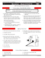
Operation -  Model HT34-PV-F 

with American Flame Electronic Ignition

For Your Safety - READ BEFORE LIGHTING:

with Proflame SIT  Electronic Ignition

WARNING:


If you do not follow these instructions exactly, a fire or explosion may result 
causing property damage, personal injury or loss of life.

To Turn Off Gas To Appliance:

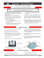
Lighting  Instructions:

  If you cannot reach your gas supplier, call the Fire 

Department.

C.

  Use only your hand to push in or turn the gas control knob. 

Never use tools. If  the knob will not push in or turn by 
hand, don't try to repair it, call a qualified service techni-
cian. Force or attempt to repair may result in a fire or explo-
sion.

D.

  Do not use this appliance if any part has been under water. 

Immediately call a qualified service technician to inspect 
the appliance and to replace any part of the control system, 
and any gas control which has been under water.

A.

  This appliance is equipped with an ignition system that 

lights the pilot burner automatically. Do not attempt to light 
the pilot by hand.

B.  BEFORE LIGHTING

 smell all around the appliance 

area for gas.  Be sure to smell next to the floor because 
some gas is heavier than air and will settle on the floor.

  What To Do If You Smell Gas:

  Do not try to light any appliance.

  Do not touch any electrical switch; do not use any 

phone in your building.

  Immediately call your gas supplier from a neighbour's 

phone. Follow the gas supplier's instructions.

1. 

Turn off remote switch.

2. 

Remove the lower Horizontal access panel.

3. 

Turn the incoming gas control valve to "Off".

4. 

Replace the lower Horizontal access panel.

1.

  STOP!  Read the safety information above on this label.

2

.  Remove the lower Horizontal access panel.

3

.  Turn Incoming gas valve to the ON" position.

4

.  Wait 5 minutes to clear out any gas.  If you smell gas, 

STOP! Follow "B" in the safety information above on this 
label.  If you don't smell gas, go to the next step.

5.

  Turn wall switch "ON".

6

If the Fireplace does not light, the System will cycle through 

two trials, (one minute audible clicking, thirty seconds of 
silence, and then another one minute of audible clicking). 
If the system locks out due to inadequate gas flow, refer to 
"Troubleshooting", Page 20.

7.


After completion of the information in the  Troubleshooting 

section, Repeat step 5.


8.


If the system will not function correctly, follow the instruc-
tions "To Turn Off Gas To Appliance" and call your service 
technician or gas supplier.

EV1 (Pilot 
burner)

EV2  (Main 
burner)

Pilot Adjust Screw

Lockout Reset Key

Diagnostic Terminal

Power

Command (Wall 
switch)

Pilot Sensor

Igniter

Ground
EV1 (Pilot burner)

EV2 (Main burner)

Gas "Out"

Gas "In"

Incoming Gas
Line,  Shut-off 
Valve

To fireplace 
Main burner

HT34-PV-F

Summary of Contents for HT34-PV Series

Page 1: ...place has been turned off Safety screens are available and can reduce the risks of severe burns C US Warning Improperinstallation adjustment alteration serviceormaintenancecancause injury or property damage Refer to this manual For assistance or additional information consult a qualified installer service agency or the gas supplier Warning What to do if you smell gas Donottrytolightanyappliance Do...

Page 2: ... systems Your new Montigo gas fireplace will give you years of durable reliable use Welcome to the Montigo family of gas fireplace products Safety Alert Key DANGER Indicates a hazardous situation which if not avoided will result in death or serious injury WARNING Indicates a hazardous situation which if not avoided could result in death or serious injury CAUTION Indicates a hazardous situation whi...

Page 3: ...ion and service work should be performed by a qualified or licensed installer plumber or gas fitter who is qualified or licensed by the state province region or governing body in which the appliance is being installed This manual covers all models and unless otherwise specified the designationHT34 PVreferstoallvariationsofthemodelabove Sections which are specific to a particular variation are mark...

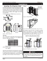
Page 4: ...ce framing depth may be reduced by 5 8 Framing Top View Front View Side View Clearances These clearances apply to all dimensions except the framed opening where the clearance to combustibles is 0 The HT34 PV Series clearances to combustible materials are Unprotected combustible walls which are perpendicular to the fireplace opening must not project beyond the shaded area shown in Figure 25 For pro...

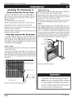
Page 5: ...onnection immediately upstream of the gas supply controls to the appliance The fireplace gas connection and the main operating gas valve is located behind the removable trim at the bottom of the unit and need only be attached to the gas line with an approved fitting as required by the applicable installation codes To access the fireplace gas connection the main burner must be removed as shown belo...

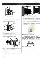
Page 6: ... over Terminations Installing The Standoffs To avoid elevated mantel temperatures all HT34 PV Series gas fireplaces are required to have the supplied standoffs installed The fireplace is supplied with two standoffs Bend and install these standoffs on top of the fireplace ensuring that the height of the standoff maintains a 6 clearance Figure 7 Installing the standoff s 1 Ensure that the two long m...

Page 7: ...cap installation for Rear Vented fireplace Figure 8b Flue collar installation for Rear Vented fireplace 4 Inner Flue Cap 7 Outer Flue Cap HT34 PV Rear Vent Use the following instructions to convert an HT34 PV for Top Vent use 1 Install the 4 inner flue cap on the top flue outlet and secure the cap in place with five screws as shown in figure 8a 2 Install the 7 outer flue cap on the top flue outlet...

Page 8: ...ls above fireplace may be hot to touch Warning When covering the upper metal portion of the fireplace up to 6 as shown Fig 24 Fig 25 with a non combustible material Please Note Thedecorativefacingmaterialsmaybesubjecttotemperaturesinexcess of 250 F This should be considered when selecting facing materials We recommend careful consideration be given to the effects of elevated mantel temperatures wh...

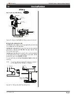
Page 9: ...s in the USA which employ the fans must be grounded in accordance with local codes or in the absence of local codes with the National Electrical Code ANSI NFPA 70 1987 For more information see the Fan Kit Installation Guide included with the fan kit NOTE If any of the original wire supplied with the appliance is replaced it must be replaced with the same type or its equivalent Figure 27a Wiring sc...

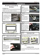
Page 10: ...e figures28g PlacetheDoorasideinasafeplacewhilemaintenance and or cleaning is being performed Figure 28g Removing and installing the glass doors Both Sides Typical Removing the Door Removing and Installing the Door Removing the door TheHT34 PVSeriesdoorisremovedinafewsimplesteps Followthese Steps below to remove the Horizontal access panel unlatch the door buckles and remove the door Replace in re...

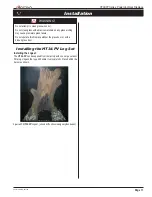
Page 11: ...ay cause premature glass failure Do not operate this fireplace without the glass door or with a broken glass door Installation Installing the HT34 PV Log Set Installing the Logset The HT34 PV can be supplied from the factory with one Large ceramic fibre log Unpack the log and handle it very carefully Place behind the burner as shown Figure29 HT34 PVLogset shownwithoptionaldesignerglassbeads ...

Page 12: ... not try to light any appliance Do not touch any electrical switch do not use any phone in your building Immediately call your gas supplier from a neighbour s phone Follow the gas supplier s instructions 1 Turn off remote switch 2 Flip down the lower trim 3 Turn the switch on the gas control to Off 4 Flip up the trim 1 STOP Read the safety information above on this label 2 Flip down the lower trim...

Page 13: ...If You Smell Gas Do not try to light any appliance Do not touch any electrical switch do not use any phone in your building Immediately call your gas supplier from a neighbour s phone Follow the gas supplier s instructions 1 Turn off remote switch 2 Remove the lower Horizontal access panel 3 Turn the incoming gas control valve to Off 4 Replace the lower Horizontal access panel 1 STOP Read the safe...

Page 14: ...s control which has been under water Operation Lighting Instructions See pages 12 to 14 Cleaning When the fireplace is first activated there may be some smoking and a visible film may be left on the glass This is a normal condition and is the result of burning of protective coatings on new metal Glass must be cleaned periodically to remove any film which is a normal by product of combustion which ...

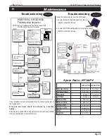
Page 15: ...wer Low voltage transformer Limit Controller Thermostat Wiring Air proving switch on combustion air blower system Vent damper if used is open and end switch made NO NO YES NO YES Unplug Pilot Burner Cable Measure Voltage at SV9500 SV9600 HSI Terminals 24VAC Nominal see INSET Replace SV9500 SV9600 Igniter warms up and glows red YES YES NO YES NO Pilot Valve opens Replace Igniter Flame Rod Assembly ...

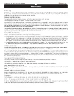
Page 16: ...jected to normal use The Gas Appliances are designed to burn gas only Burning conventional fireplace fuels such as wood coal or any other solid fuel will cause damage to the Gas Appliance will produce excessive temperatures and will result in a fire hazard Limitations On Liability It is expressly agreed and understood that The Companies sole obligation and purchaser s exclusive remedy under this W...

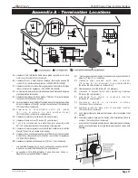
Page 17: ...t minimum in the United States 6 feet 1 8 m minimum in Canada L clearance to non mechanical air supply inlet to building or the combustion air inlet to any other appliance 16 inches 41 cm minimum for appliances 100 000 BTU H 30kW M clearance to mechanical air supply inlet 6 feet 1 8 m minimum N clearance above paved sidewalk or a paved driveway located on public property 7 feet 2 1 m minimum P cle...

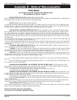
Page 18: ...e directly in line with the exhaust vent terminal for the horizontally vented gas fueled heating appliance or equipment The sign shall read in print size no less than one half 1 2 inch in size GAS VENT DIRECTLY BELOW KEEP CLEAR OF ALL OBSTRUCTIONS 4 INSPECTION The state or local gas inspector of the side wall horizontally vented gas fueled equipment shall not approve the installation unless upon i...

Page 19: ...Page 19 HT34 PV Series Power Vent Gas Fireplace Part No XG0530 041510 Notes ...

Page 20: ...Canadian Heating Products Inc Langley BC V4W 4A1 Montigo Del Ray Corp Ferndale WA 98248 XG0530 041510 ...

Reviews: