Page 4
HT34-PV Series Power Vent Gas Fireplace
Part No. XG0530 - 041510
Installation
Installing The Fireplace Shell
The fireplace may be installed in any location that maintains proper clear-
ances to air conditioning ducts, electrical wiring and plumbing. Safety,
as well as efficiency of operation, must be considered when selecting
the fireplace location. Try to select a location that does not interfere
with room traffic, has adequate ventilation, and offers an accessible
pathway for Power Vent installation. Refer to
page 4
-
Vent Installation
for more information.
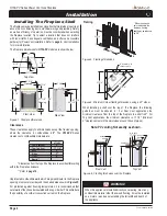
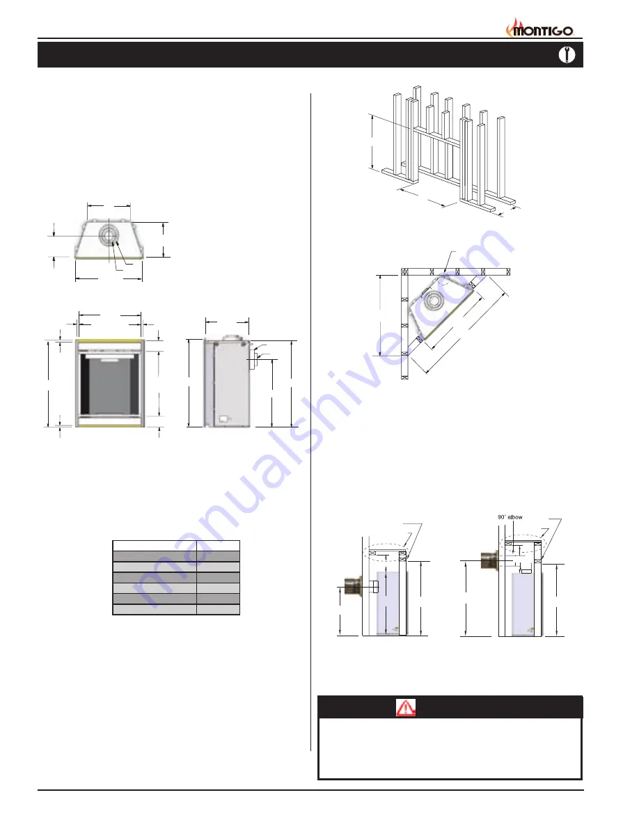
The fireplace dimensions for
HT34-PV
models are shown below:
When installing a shelf over the top of the fireplace, the following
guidelines must be adhered to: For Rear Vent applications the
minimum clearance from the top of the fireplace to a shelf is 9". For
Top Vent applications, the minimum clearance is 17 1/2". (
Minimum
2" clearance must still be maintained around the vent pipes.
)
Figure 4.
Framing for shelves over the fireplace.
Top Vent
Figure 3.
Minimum Corner framing dimensions, using a 45° elbow.
Figure 2.
Framing dimensions.
* When sheetrock is
not used behind the
fireplace, framing
depth may be reduced
by 5/8"
Framing
Top View
Front View
Side View
Clearances
These clearances apply to all dimensions
except the framed opening
,
where the clearance to combustibles is
0"
. The
HT34-PV
Series
clearances to combustible materials are:
Unprotected combustible walls which are perpendicular to the fireplace
opening, must not project beyond the shaded area shown in
Figure 25
.
For protection against freezing temperatures, it is recommended that
outer walls of the chase be insulated with a vapor barrier. This will reduce
the possibility of a cold-air convection current on the fireplace.
Figure 1.
Fireplace dimensions.
Rear Vent
* Clearances from the top of the fireplace to a combustible ceiling
within the fireplace enclosure.
** Refer to
page 14
.
WARNING!
When this appliance is installed directly on carpeting, tile or any
combustible material other than wood flooring, it must be installed
on a metal or wood panel extending the full width and depth of
the appliance.
52 5/8”
34”
37 3/8”
0” clearance to
corners only
20”
53 3/4”
34”
Note: PV venting Not exactly as shown.
17 3/8”
48”
7”
4”
40 1/4”
47 3/8”
47 7/8”
1 1/4”
1”
31 3/8”
Opening
1 1/4
”
1 1/4”
5 1/2”
5 1/4”
37 1/8”
Opening
17 3/8”
22”
9 1/2”
CL
7”
4”
33 7/8”
M
T
9”
S
Header
Header
Shelf
MEL Short
Shelf
L
M
17 1/2”
Power Vent
HT34-PV
Top - Rear Vent *
9"
Top - Top Vent
17 1/2”
Back
2"
Sides
1"
Floor
0"
Mantle**


