background image

Page 11

L-Series DF Gas Fireplace

Part No. XG0180

f i r e   f e a t u r e

Installation

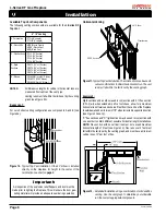
Important:  Corner Installation is available only for 

Top Vent Units.

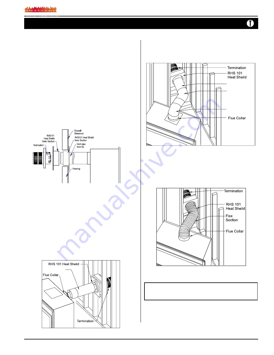
Figure 20.


Corner installation.


Figure 21.


Flex installation.

 (NG Models Only)

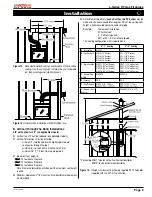
2.  45° Corner Installation.

  Attach an PEL-90 (90° elbow) directly onto the flue collar, and attach 

it to the PEL-45 (45° elbow). Cut the PXT-18 to suit and insert it into 

the PEL-45. Slide the fireplace into position, and then connect it to 

the exterior termination.


3.  Corner Installation — 45° or less.

  Use  an  PTO-3  termination  and  an  PFL-1  or  PFL-2  (12"  or  24" 

compressed length) and a frame, if appropriate.


Flex may be turned to 

obtain desired degree of angle required but must not exceed 45°.

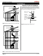
Figure 19a.


Extended installation.


PXT-12

PXT-18

PEL-45 Elbow

PEL-90 Elbow

Rear Vent Venting Runs

The L-Series DF Rear Vent 

has three possible installations which do 

not require vertical lift, all of these installations require that you install 

the RHS101 heat shield. 

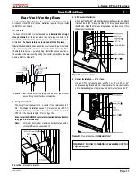
Heat Shield

 The heat shield (RHS101) must be used on 

all installations straight 

through the wall

, at the point where the vent pipe connects to the 

termination.  With  the  heat  shield,  proper  vent  clearances  can  be 

maintained. 

The heat shield is not included with the fireplace.

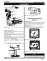
To install the heat shield, slide one section over the vent pipe on the inside 

of the wall opening, with the circular portion 

inside the wall cavity

. Screw 

the shield in place over the wall opening. Install the second section on 

the outside of the wall opening sliding the circular portion into the wall 

opening. Refer to Figure 19.

Figure 19.

  Heat Shield. Install by sliding over the vent pipe where it 

passes through combustible construction.

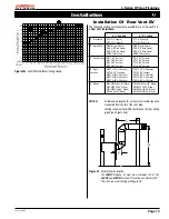
1.  Straight Installation.

  The height from the hearth to the center of the termination is 21 

3/4". For straight installations use a 12" extension pipe (PXT-12) 

with female/female connections. For shorter installations, cut the 

PXT-12 to the desired length. Refer to figure 19a.


  Ensure that the RHS101 heat shield is installed before attaching 

the pipe to the termination.
Note:

  For Rear Vent models, maximum horizontal run with no 

vertical lift must never exceed 12".

Summary of Contents for L38DF series

Page 1: ...phone Follow the gas supplier s instructions If you cannot reach your gas supplier call the fire department For Your Safety Do not store or use gasolineorotherflammable vapors and liquids in the vicin...

Page 2: ...or glass doors Use of any component part not manufactured or approved by Montigo in combination with this Montigo fireplace system Installation other than as instructed in this manual Consult your lo...

Page 3: ...t be installed on a metal or wood panel extending the full width and depth of the appliance Top View Front View Side View Unprotected combustible walls which are perpendicular to the fireplace opening...

Page 4: ...C a manifold pressure of 3 5 W C Propane Gas requires a minimum inlet gas supply pressure of 11 W C a manifold pressure of 10 W C Provision must also be made for a 1 8 N P T plugged tapping and be ac...

Page 5: ...termination where temperatures are highest 2 Attach to the faceplate of the termination using four sheet metal screws Installing Heat Guards over Terminations Installing The Remote Switch The L Serie...

Page 6: ...d fireplace Figure 7b Flue collar installation for Top Vented fireplace Figure 8a Flue cap installation for Rear Vented fireplace Figure 8b Flue collar installation for Rear Vented fireplace L Series...

Page 7: ...acceptable installation Figure 9a L38DF Top Vent Venting Graph L42DF Example A Acceptable Installation If the vertical dimension from the hearth is 84 and the horizontal run to the wall flange of the...

Page 8: ...installation Thesolidsectionscanbeusedin variouscombinationstoobtainthedesiredventrun Thevent run must fall within the limits set by the venting graph Figure 12 Extended Installation using a combinati...

Page 9: ...wo offsets each offset has two 90 bends may be made and shall not exceed total length of 25 of the vertical vent height when measured center to center of piping Example Typical vent installation 20 ve...

Page 10: ...ith 1 offset 1 offset two 90 bends Figure 18 Reducing Vertical Vent from 5 8 to 4 7 Reduced Vertical Installation It is possible to reduce vertical vent runs from 5 8 venting to 4 7 venting Reducedver...

Page 11: ...hield Heat Shield The heat shield RHS101 must be used on all installations straight through the wall at the point where the vent pipe connects to the termination With the heat shield proper vent clear...

Page 12: ...tallation If the vertical dimension from the floor of the fireplace is 78 and the horizontal run to the wall flange of the vent termination is 108 this would not be an acceptable installation Figure 2...

Page 13: ...MTO 3F 3 Length PTO 3 3 Length PTO 3F 3 Length B Stucco Kits MSR Stucco Frame BSR 4 4 Brick Frame BSR 6 6 Brick Frame MOSR Stucco Can MSR Stucco Frame BSR 4 4 Brick Frame BSR 6 6 Brick Frame MOSR Stuc...

Page 14: ...cing materials may be subject to temperatures in excess of 250 F This should be considered when selecting facing materials We recommend careful consideration be given to the effects of elevated mantel...

Page 15: ...d with the same type or its equivalent Figure 27b Wiring schematic for optional fans Figure 27a Wiring for optional fans Removing and Installing the Door Removing the door The door is held in place by...

Page 16: ...ff Gas To Appliance Operation Model L Series DF 3 Push in gas control knob slightly and turn clockwise to Off Do not force 4 Flip up the lower trim 1 Turn off remote switch 2 Flip down the lower trim...

Page 17: ...try to light any appliance Do not touch any electrical switch do not use any phone in your building Immediately call your gas supplier from a neighbour s phone Follow the gas supplier s instructions 1...

Page 18: ...ting Instructions To Turn Off Gas To Appliance 1 STOP Read the safety information above on this label 2 Flip down the lower trims 3 If the switch on the control module is set to Continuous Pilot Off t...

Page 19: ...ll a qualified service technician to inspect the appliance and to replace any part of the control system and any gas control which has been under water Operation Lighting Instructions See pages 16 17...

Page 20: ...r until the bubbling stops completely Figure 34 Pilot Burner Troubleshooting The following is a troubleshooting chart of possible problems PROBLEM CORRECTIVE ACTION Noisy Pilot Flame Locate pilot adju...

Page 21: ...jected to normal use The Gas Appliances are designed to burn gas only Burning conventional fireplace fuels such as wood coal or any other solid fuel will cause damage to the Gas Appliance will produce...

Page 22: ...t minimum in the United States 6 feet 1 8 m minimum in Canada L clearance to non mechanical air supply inlet to building or the combustion air inlet to any other appliance 16 inches 41 cm minimum for...

Page 23: ...Spare Parts L SeriesDF L38DF L42DF NG Gas Valve RGC1006 RGC1006 LP Gas Valve RGC1005 RGC1005 NG Pilot RPA020 RPA020 LP Pilot RPA021 RPA021 Burner NG RBL3801 RBL4201 Burner LPG RBH3802 RBL4202 ROR1151...

Page 24: ...Canadian Heating Products Inc Langley BC V4W 4A1 Montigo Del Ray Corp Ferndale WA 98248 XG0180 033007...

Reviews: