Page 15
L-Series DF Gas Fireplace
Part No. XG0180
f i r e f e a t u r e
Installation
Wiring
Gas Control and Pilot Wiring
L-Series DF-I
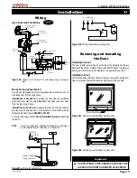
Figure 26.
Wiring for the L-Series DF-I with Honeywell gas control and
pilot.
Wiring for the
optional
Fan Kit
All L-Series DF fireplaces may be equipped with optional fan kits for
circulating heat into the living space.
Installations in Canada
which employ the fans must be electrically
grounded in accordance with
CSA C22.1 Canadian Electrical Code
Part 1 and/or Local Codes.
Installations in the USA
which employ the fans must be grounded in
accordance with local codes or, in the absence of local codes, with the
National Electrical Code,
ANSI/NFPA 70-1987.
For more information see the
Fan Kit Installation Guide
included with
the fan kit.
NOTE:
If any of the original wire supplied with the appliance is replaced, it
must be replaced with the same type, or its equivalent.
Figure 27b.
Wiring schematic for optional fans.
Figure 27a.
Wiring for optional fans.
Removing and Installing
the Door
Removing the door:
The door is held in place by a lip on the top of the metal frame and two
buckles at the bottom. Release the buckles and lift the door carefully up
and away from the front of the fireplace.
See figures 28a and 28b.
Installing the door:
Hook the top edge of the door frame into place. Lower and rest the door
frame in place and fasten the buckles.
See figures 28a and 28b.
Figure 28b.
Removing and installing the glass door.
Figure 28a.
Removing and installing the glass door.
Cautions:
DO NOT OPERATE THIS FIREPLACE WITHOUT THE
GLASS DOOR OR WITH A BROKEN GLASS DOOR.
Cautions:
Honeywell (Q3450)
Pilot Assembly
Pilot Electrical
Harness Connector
Honeywell Gas
Control (SV9501M)
Junction Box Cover
Fuse
Gas Control
Connector
Junction Box
115VAC
24VAC
40 VA
Transformer
Black
White
Green
Gnd Screw
Limit Switch
Wall Switch
Fan Plug
Receptacle
5/1/60 Supply
G
L1 L2
G
L2-WH
L1-BLK
p g
Quick Connect
lu to motor

