background image

Page 5

L52DF* Indoor Gas Fireplace

XG0185 - 100511.1

Installation

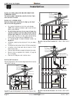
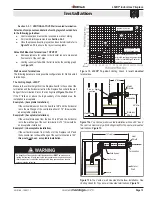
Section 1:  Installation Overview and Product Dimensions

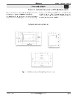
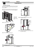
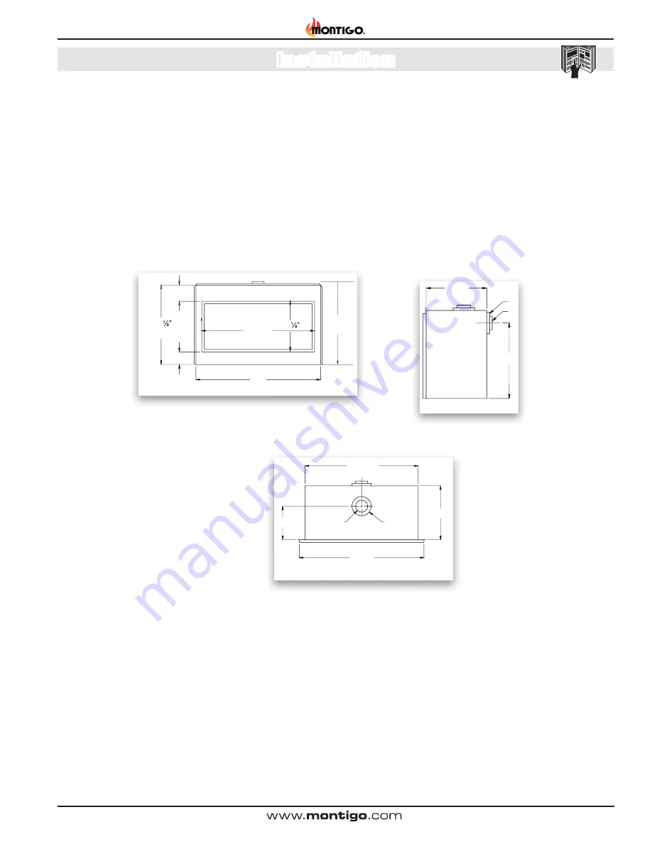
Figure 1.


Unit Dimensions shown with nailing flange 


(Tolerance 

± 

"

)

Please review the Installation Checklist on

 Page 4

 for general information 

on preparing for a successful installation of your fireplace.
The 

L52DF* 

fireplace may be installed in any location that maintains 

proper clearances to air conditioning ducts, electrical wiring and plumbing.  

Safety, as well as efficiency of operation, should be considered when 

selecting the fireplace location.  Try to select a location that does not 

interfere  with  room  traffic,  has  adequate  ventilation  and  offers  an 

accessible path for Direct Vent installation.

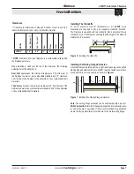
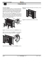
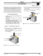
The fireplace dimensions are shown below:

52”

33 

47”

21   

5 ¼

34 ½”

Faceplate

Firebox

Front View

52”

21 ¾” 

I

J

14”

47 ½"

Top View

21 ¾”

5”

8”

28”

Side View

6 ¾”

Summary of Contents for L52-DF

Page 1: ...ent hazard Battery hazard Rotating parts Low temperature Strong magnetic field Optical radiation Non ionizing radiation Radiation Hazardous to the Environment Danger of harming your hands Irritant Cutting Watch your step Slippery floor High temperatures Glass hazard Danger of suffocation High voltage Toxic Flammable materials Corrosive Fork lift trucks Danger overhead crane Explosion risk Oxidisin...

Page 2: ... Rear Vent no elbows or offsets 16 Rear Vent Wall mounted termination two elbows 16 Section 3 3 2 Venting Components 17 Section 3 3 3 Heat Shields 18 Installing a RHS8 Wall Mounted Heat Shield 18 Installing a RHS101 Wall Mounted Heat Shield 18 Section 4 Wiring 19 20 SIT Nova 820 gas control and pilot 19 SIT Proflame gas control and pilot 19 Installing remote On Off wall switch 20 Installing HFK Fa...

Page 3: ...efer to your rating plate to verify included options Throughout this instruction guide instructions are applicable to all models designated as L52DF unless otherwise noted Warranty and Installation Information See Appendix B The Montigo warranty will be voided by and Montigo disclaims any responsibility for the following actions Modification of the fireplace and or components including Direct Vent...

Page 4: ... must conform to the local codes or in the absence of local codes to the current version of National Fuel Gas Code ANSI Z223 1 NFPA 54 Electrical Installations must conform to the local codes or in the absence of local codes to the current version of the National Electrical Code ANSI NFPA 70 See Appendix C for installation within the State of Massachusetts Installation and repairs should be done b...

Page 5: ...DF fireplace may be installed in any location that maintains properclearancestoairconditioningducts electricalwiringandplumbing Safety as well as efficiency of operation should be considered when selecting the fireplace location Try to select a location that does not interfere with room traffic has adequate ventilation and offers an accessible path for Direct Vent installation The fireplace dimens...

Page 6: ...ith Alcove Above Fireplace Frame in the enclosure for the unit with framing materials The framed opening for the assembled fireplace is 52 wide x 39 high x 25 deep see Figure 2 NOTE When constructing the framed opening please ensure there is access to install the gas line when the unit is installed See Figure 21 MIN 84 Header 3 MIN 1 Floor Alcove area over Fireplace Top Vent Non Combustible Materi...

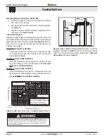
Page 7: ... The fireplace is supplied with two standoffs Bend and install these standoffs on top of the fireplace ensuring that the height of the standoff maintains a 6 clearance Figure 6 Installing the standoff s Figure 7 Installing the Nailing Flange Extension Installing the Nailing Flange Extension Once the fireplace is placed into the rough framed opening the supplied NailingFlangeExtension PartNo L52087...

Page 8: ...hown TheseareinstalledwiththeWideflanges facing the center of the fireplace opening and the shallow flange toward inside of room These are also fastened with nails or screws flush with framing as shown in Figure 8 and Inset Figure8a CombustibleFramingTopHeatShieldL52FS02x1 one1 pc Figure 8b Combustible Framing Heat Shield completed Step 2 Next fasten the Top shield L52FS02x1 with the Wide flange f...

Page 9: ... Flue Cover Plate Flue Gasket Flue Cover Plate 8 Outer Flue Collar 5 Inner Flue Collar Montigo supplies a variety of direct venting and termination options The direct vent termination location MUST be selected such that it is the highest point in the venting assembly It should also be selected such that it provides the shortest vent run possible Should it be impossible to ensure that the terminati...

Page 10: ...mum termination point is 32 above the fireplace NOTE if the maximum termination height is used the flame pattern may be affected The Vertical termination must be a minimum 2 higher than where the termination exits the roofing materials asphalt shingles cedarshakes etc Thisdistanceshouldbemeasured from the high side of the roof slope where the flue flashing intersects the roofing materials see Figu...

Page 11: ...Page 11 L52DF Indoor Gas Fireplace XG0185 100511 1 Installation Figure 10c Rear vent Roof mounted venting 1 90 bend Support ring Support plate 32 max MEXT Sections Termination 12 Max PVTK1 ...

Page 12: ...o the MOSR frame as shown here from the inside and attach to the MOSR by installing a min quantity of 4 bolts into the threaded nuts on the MOSR Frame Installation of termination frame at time of framing in Masonry Terminations with a BSR frame allow the installation of the frame in masonry prior to the installation of the termination 1 Frame the BSR opening to 12 x 12 2 Secure the BSR Frame to th...

Page 13: ...all mounted Multi elbow installation See Venting Graph for Top vent wall mounted terminations Figure 12 Section 3 3 1 VENTING LAYOUT Wall mounted termination Selectionofcomponentsanddetailsofventinglayoutshouldadhere to the following guidelines Vent terminations must not be recessed in walls or siding For Heat Shield requirements see Section 3 3 3 Once the proposed venting layout has been determin...

Page 14: ...Page 14 L52DF Indoor Gas Fireplace XG0185 100511 1 Installation Figure 13c TopVented wallmountedRetractedMulti elbowinstallation See Venting Graph for Top vent wall mounted terminations Figure 13 ...

Page 15: ...o the PEL 45 45 elbow Cut the PXT 18 to suit and insert it into the PEL 45 Slide the fireplace into position and then connect it to the exterior termination PEL 45 Elbow PEL 90 Elbow PXT 18 45 or less Corner Installation Use an PTO 3 termination and an PFL 1 or PFL 2 PFL 2 12 or 24 compressed length and a frame if appropriate Flex may be turned to obtain desired degree of angle required but must n...

Page 16: ...n If the vertical dimension from the hearth is 42 and the horizontal run to the wall flange of the vent termination is 108 this would not be an acceptable installation Example C Unacceptable Installation If the vertical dimension from the floor of the fireplace is 60 and the horizontal run to the wall flange of the vent termination is 168 this would not be an acceptable installation Figure 15a Rea...

Page 17: ...lt your Building Envelope Engineer or Waterproofing Consultant for further recommendations Section 3 3 2 VENTING COMPONENTS The following components and associated Montigo part numbers for installation of a roof or wall mounted termination Use only Montigo Vent Components Use of non Montigo parts will VOID the warranty and may impede operation of the fireplace Use any combination of rigid and flex...

Page 18: ...8 Installation Minimum requirements RHS8 Heat Shield 1 Min Both sides Typical 1 Min 1 Min Combustible Framing RHS8 Heat Shield 36 Min 60 Min Termination Drywall sheetrock RHS101 Heat Shield inner Section RHS101 Heat Shield Outer Section Combustible framing Termination Drywall sheetrock RHS101 Heat Shield inner Sectio RHS101 Heat Shield Outer Section Vent pipe from fireplace Figure 17b RHS101 Insta...

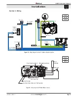
Page 19: ...pe Chassis connection 120 Vac INPUT 7 Vdc STABILIZED SUPPLY OUTPUT ON OFF ON OFF IPI CPI BATTERY DC SUPPLY VALVE GROUND DFC CPI IPI MODE Not Used Models L52DFN F L52DFL F Models L52DFN L52DFL Manifold Pressure Test Connection Wall Switch Power Generator Pilot Adjustment Screw Inlet Pressure Hi Lo Adjustment Knob Gas Control Knob Shown in Pilot position Figure 19 Wiring Diagram for SIT Nova 820 gas...

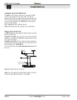
Page 20: ...an Kit All L52DF fireplacesmaybeequippedwithoptionalfankitsforcirculating heat into the living space Installations in Canada which employ the fans must be electrically grounded in accordance with CSA C22 1 Canadian Electrical Code Part 1 and or Local Codes Installing the remote On Off Wall Switch The L52DF gas valve may be connected to a wall switch Do NOT connect any external power to the remote ...

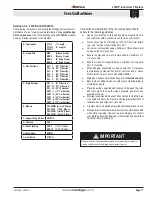
Page 21: ... a hose barb Q Q Montigo requires a service shut off valve be located in an accessible location to isolate the gas supply Q Q Only install gas shut off valves approved for use by the state province or other governing body in which the fireplace is being installed Section 5 3 GAS CONNECTION Q Q See Figure 21 for location of gas line access Q Q Flexiblegasconnectorsmustnotexceed3feetinlength unless ...

Page 22: ...o combustible materials New technology to meet consumer and government demands for the wise use of energy has prompted us to manufacture many models of fireplaces which are hot fuel and energy efficient Please be aware temperatures over the mantel will rise above normal room temperature and walls above fireplace may be hot to touch Side wall clearances are 3 Combustible surrounds may be installed ...

Page 23: ...p 5 Ensure the tool is firmly in the lower end of the slot asshown Thenpulltoward you Caution hold the tool securely 3 Step 6 Pull hard if necessary to release the spring tension Caution The latch springs backwithforce holdthetool securely 4 Step 7 Remove the tool from the latch slot Ensure the latches are hanging freely the hook end is released from the bottom of the door Repeat all 4 steps for t...

Page 24: ...es hastheoptionofinstallingtheoptionalculturedrocks or firestones As described below CAUTION the firestones or cultured rocks cannot cover the burners Doing so produces an undesirable uneven flame pattern and eventual sooting Install as shown Figure 25 to 25a Figure 25 Completed firestone installation Note DO NOT place ANY firestones on top of the burners Figure25a Operatinggasfireplacewithfiresto...

Page 25: ... access panel with American Flame Electronic Ignition For Your Safety READ BEFORE LIGHTING Lighting Instructions 1 STOP Read the safety information above on this label 2 Lift out the lower Horizontal access panel 3 Push in gas control knob and turn clockwise to OFF 4 Wait five 5 minutes to clear out any gas Smell for gas including near the floor If you then smell gas STOP Follow B in the safety in...

Page 26: ...cal switch do not use any phone in your building Immediately call your gas supplier from a neighbour s phone Follow the gas supplier s instructions 1 STOP Read the safety information above on this label 2 Remove the lower Horizontal access panel 3 Turn Incoming gas valve to the ON position 4 Wait 5 minutes to clear out any gas If you smell gas STOP Follow B in the safety information above on this ...

Page 27: ...most effective products is Kel Kem Silicone seals on inner door during initial firing will off gas leaving a visual deposit of a white substance on combustion chamber walls This can easily be removed from the chamber walls using normal household products Use a vacuum cleaner or whisk broom to keep the control compartment burner and firebox free from dust and lint Hi Lo Burner Adjustment SIT Nova 8...

Page 28: ...l switch for proper connection SIT Proflame System The following is a troubleshooting chart of possible problems PROBLEM SOLUTION Pilot won t ignite or spark Check the on the batteries on the remote or the receiver Check the green LED on AC adaptor Check the green ground wire under the valve Main burner will not light Check the wiring on the valve as per diagram Figure 18 Fan not working Make sure...

Page 29: ...or Assembly RDTL52 Locate Model and Serial number on Unit ID tag and contact dealer SIT IPI N G Gas Valve RGC3044 L P Gas Valve RGC3045 N G Gas Valve Stepper Motor RGC3033 L P Gas Valve Stepper Motor RGC3034 N G Pilot Assembly RPA033 L P Pilot Assembly RPA034 Igniter Probe Assembly RGC3052 Flame Sensor Rod Assembly RGC3053 Burner N G Burner Orifice RORO53 x 4 L P Burner Orifice RORO63 x 4 Pilot Tu...

Page 30: ...iance 100 000 BTU H 30 KW 12 inches 12 inches M clearance to forced air supply inlet 6 feet 3 feet above air inlet N clearance above paved sidewalk or paved driveway located on public property 7 feet 7 feet P clearance under veranda porch deck or balcony 22 inches to combustibles 16 inches to non combustibles 22 inches to combustibles 16 inches to non combustibles Q clearance above roof 2 feet 2 f...

Page 31: ...ust be subjected to normal use The Gas Appliances are designed to burn gas only Burning conventional fireplace fuels such as wood coal or any other solid fuel will cause damage to the Gas Appliance will produce excessive temperatures and will result in a fire hazard Limitations On Liability It is expressly agreed and understood that The Companies sole obligation and purchaser s exclusive remedy un...

Page 32: ...ht of eight 8 feet above grade directly in line with the exhaust vent terminal for the horizontally vented gas fueled heating appliance or equipment The sign shall read in print size no less than one half 1 2 inch in size GAS VENT DIRECTLY BELOW KEEP CLEAR OF ALL OBSTRUCTIONS 4 INSPECTION The state or local gas inspector of the side wall horizontally vented gas fueled equipment shall not approve t...

Page 33: ...Page 33 L52DF Indoor Gas Fireplace XG0185 100511 1 Notes ...

Page 34: ...Ferndale Washington TF 1 800 789 6236 FX 1 866 3000 0927 Langley British Columbia TF 1 800 378 3115 FX 1 604 607 6462 XG0185 050611 1 L52DF Residential Gas Fireplace ...

Reviews: