Page 13
P/N XG0206
M40DV-CR/CL Corner Gas Fireplace
Finishing Around the Fireplace
Combustible mantels and mouldings may be safely installed over the
top and on the front of the fireplace provided that they do not project
beyond shaded area shown in
Figure 20a
. Side wall clearances are
0". Combustible surrounds may be installed with 0" clearance to the
side of the fireplace as shown in
Figure 20b
.
Fireplace Facing
When selecting the finish material for your fireplace, it is important to
remember the following:
LOUVRE TRIMS AND FIREPLACE FRAME
MUST NOT BE OBSTRUCTED IN ANY WAY - to do so restricts
the air supply for the control compartments and heat exchanger
it also prevents access for servicing controls.
The face of the fireplace may be painted to match the room decor,
provided you use a heat-resistant paint. Decorative facing must not
extend past the fireplace opening at all, because it will interfere with
the access to retainers for removal of glass door.
When using a tile
facing, It is required not to tile over the outside frame of the fire-
place, as this will obstruct the door removal.
See Figure 20c.
Installation
Mantels & Surrounds
NOTE:
Mantel clearances are for fire hazard prevention to combus-
tible materials.
New technology, to meet consumer and government demands for the
wise use of energy, has prompted us to manufacture many models of
fireplaces which are hot, fuel and energy efficient.
Please be aware; temperatures over the mantel will rise above normal
room temperature and walls above fireplace may be hot to touch.
We recommend careful consideration be given to the effects of
elevated mantel temperatures which may be in excess of product
design, for example: candles, plastic or pictures. This can cause melt-
ing, deformation, discoloration or premature failure of T.V. and radio
components.
Painting:
Figure 20a. Combustible mantles and facings.
Figure 20b. Combustible surrounds. Top view.
Special care is recommended by the Master Painters and Decorators
Association, when painting the fireplace surrounds, to select and ap-
ply a quality
Alkyd sealer
prior to the applying of latex paints. This is
to prevent leaching of water from evaporation and causing a brownish
staining effect to paint over coats.
Part
Size
5"/8" Venting 4"/7" Venting
A - Termination
n/a
PVTK-1
MVTK-1
B - Flex sections
12" length
PFL-1
MFL-1
24" length
PFL-2
MFL-2
36" length
PFL-3
MFL-3
48" length
PFL-4
MFL-4
C - Solid sections
12" length
PEXT-1
MEXT-1
24" length
PEXT-2
MEXT-2
36" length
PEXT-3
MEXT-3
48" length
PEXT-4
MEXT-4
D - Support Ring
& Plate
PSPXT-8
MSPXT-7
E - Firestop
PS-8
FS-7
F - Roof Flashing
(1/12-7/12 pt.)
PRF-7
MRF-7
(7/12-12/12 pt.)
PRF-12
MRF-12
G - Vertical
(5"/8" to 4"/7")
PVA5487
Vent Reducer
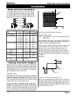
Figure 19. Reduced Vertical venting application from 5"/8" to 4"/7".
Reduced Vertical Installation
It is possible to reduce vertical vent runs from 5"/8" venting to
4"/7" venting. Reduced vertical venting may only be used when
the installation exeeds 12 feet and terminates through the roof
,
and if the vertical vent reducer is used with the following venting
configuration.


