background image

P/N XG0205

Page 12

M40DV-PFC Peninsula Gas Fireplace

Installation

Installation Of Vertical Vent DV

 

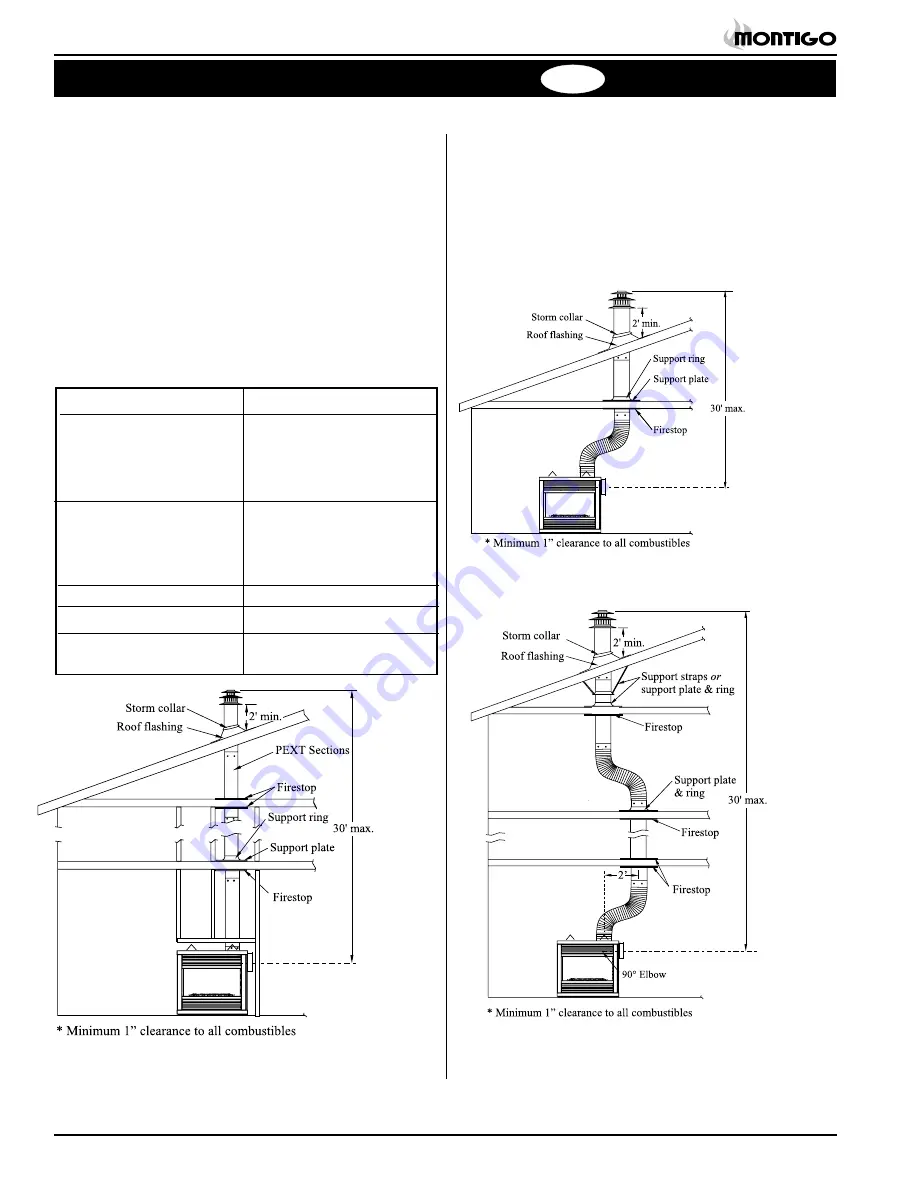
Vertical Terminations must be installed: 


minimum 2' (two feet) above the highest point where


vent passes through the roof.


minimum 6' (six feet) from a mechanical air inlet


minimum 18" (1 1/2 feet) from a parapet wall.

  Maximum vent height is 30 feet above fireplace.

  Note: Flame characteristics will change if the maximum vent 

height is used.


Minimum 

clearance to combustible construction around the 

vent pipe is 1"

 on all sides must be maintaned, except on hori-

zontal venting where the 

top

 of the pipe must have a clearance of 

at least 2".

 

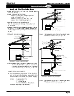
A maximum of two offsets

 (each offset has two 90° bends)

 may be 

made if the length of the offsets does not exceed 25% of the vertical 
vent height, when measured center to center of piping.

  Example: 

Typical vent installation.


30' vertical vent


2 - 2' offsets required


25% of 30' = 7-1/2' max. offset allowed

  This venting configuration meets requirements.

  A - Termination 

PVTK-1

  B - Flex sections 

PFL-1 (12" section)


PFL-2 (24" section)


PFL-3 (36" section)


PFL-4 (48" section)

  C - Solid sections 

PEXT-1 (12" section)


PEXT-2 (24" section)


PEXT-3 (36" section)


PEXT-4 (48" section)

  D - Support Ring & Plate 

PSPXT-7 (8" dia.)

  E - Firestop 

PS-8 (8" dia.)

  F - Roof Flashing 

PRF-7 (1/12 - 7/12 pitch)


PRF-12 (7/12 - 12/12 pt.)

Figure 18. Vertical venting using 2 offsets (1 offset= two 

90° bends).


     * If reducing to 4"/7" venting see figure 19.

Figure 17. Vertical venting using 1 offset (1 offset= two 

90° bends).


    * If reducing to 4"/7" venting see figure 19.

Figure 16. Straight, vertical venting. 


     * If reducing to 4"/7" venting see figure 19.

Top Vent

Summary of Contents for M40DV-PFC (MH)

Page 1: ... and read all instructions prior to installation C US For Your Safety Do not store or use gaso line or other flammable vapors and liquids in the vicinity of this or any other appliance WARNING Improper installation adjustment alteration service or maintenance can cause injury or property damage Refer to this manual For assistanceoradditionalinformation consultaqualifiedinstaller service agency or ...

Page 2: ...DANGER Indicates a hazardous situation which if not avoided will result in death or serious injury WARNING Indicates a hazardous situation which if not avoided could result in death or serious injury CAUTION Indicates a hazardous situation which if not avoided could result in minor or moderate injury NOTICE Used to address practices not related to personal injury Important Used to address practice...

Page 3: ...onsibility for the following actions Modification of the fireplace and or components including Direct Vent assembly or glass doors Use of any component part not manufactured or approved by Montigo in combination with this Montigo fireplace system Installation other than as instructed in this manual Consult your local Gas Inspection Branch on installation require ments for factory built gas firepla...

Page 4: ...t project beyond the shaded area shown in Figure 20b For protection against freezing temperatures it is recommended that outer walls of the chase be insulated with a vapour barrier This will End View Side View Figure 2a Framing dimensions Clearances The M40DV PFC clearances to combustible materials are Top 8 Rear 1 Floor Combustible Mantle 6 Flue Cover 1 1 2 Clearance from the top of the fireplace...

Page 5: ...ly piping system during any pressure testing of that system at test pressures in excess of 1 2 psig 3 5 kPa The appliance must be isolated from the gas supply piping system by closing its individual manual shutoff valve during any pressure testing of the gas supply piping system at test pressures equal to or less than 1 2 psig 3 5 kPa Installation Vent Installation This section covers the installa...

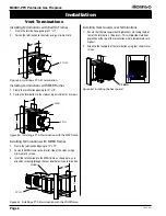
Page 6: ...crews 12 12 MSR Figure 4b Installing a PT0 3 termination with the MSR frame Figure 4c Installing a PT0 3 termination with the MOSR frame 12 12 12 MOSR Installing Terminations with MOSR Frames 1 Frame the termination opening to 12 x 12 2 Fasten the MSR frame to the interior side of the studs using a minimum of 4 screws 3 Insert the termination into the MSR frame as shown here and attach by screwing...

Page 7: ... an acceptable installation Example B Acceptable Installation If the vertical dimension from the hearth is 72 and the horizontal run to the wall flange of the vent termination is 36 this would be an acceptable installation Example C Unacceptable Installation If the vertical dimension from the floor of the fireplace is 48 and the horizontal run to the wall flange of the vent termination is 108 this...

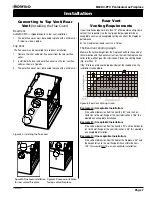
Page 8: ...n with one another to obtain different possible horizontal length instal lations NOTE Flex section must not exceed maximum horizontal length of 4 feet and for this application the top clearance is to the Long Vent Runs For longer or more complex vent runs vertical lift is required First ensure that the planned run is acceptable using the Vent Graph Plan out the required components using the chart ...

Page 9: ... of the pipe must have a clearance of at least 2 2 Offset Vertical Installations Amaximumoftwooffsets eachoffsethastwo90 bends may be made if the length of the offsets does not exceed 25 of the vertical vent height when measured center to center of piping Example Typical vent installation 30 vertical vent 2 2 offsets required 25 of 30 7 1 2 max offset allowed This venting configuration meets requi...

Page 10: ...n to the wall flange of the vent termination is 120 this would be an acceptable installation Example B Acceptable Installation If the vertical dimension from the hearth is 66 and the horizontal run to the wall flange of the vent termination is 30 this would be an acceptable installation Example C Unacceptable Installation If the vertical dimension from the floor of the fireplace is 48 and the hori...

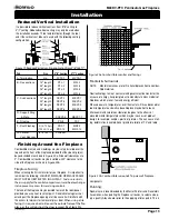
Page 11: ...ive foot chase allow for a maxi mum horizontal run of twelve and one half feet from the centre of the fireplace to outside wall and a minimum of 7 6 when retracted in opposite direction See Figure 14a and 14b D flex sections and E solid sections may be used in conjunction with one another to obtain different possible horizontal length instal lations NOTE Flex section must not exceed maximum horizo...

Page 12: ...e made if the length of the offsets does not exceed 25 of the vertical vent height when measured center to center of piping Example Typical vent installation 30 vertical vent 2 2 offsets required 25 of 30 7 1 2 max offset allowed This venting configuration meets requirements A Termination PVTK 1 B Flex sections PFL 1 12 section PFL 2 24 section PFL 3 36 section PFL 4 48 section C Solid sections PE...

Page 13: ... fuel and energy efficient Please be aware temperatures over the mantel will rise above normal room temperature and walls above fireplace may be hot to touch We recommend careful consideration be given to the effects of elevated mantel temperatures which may be in excess of product design for example candles plastic or pictures This can cause melt ing deformation discoloration or premature failure...

Page 14: ... back of the fireplace Refer to figure 22b Removing the Doors Side louvre assembly End louvre assembly Figure 22a Removing the louvre assemblies Figure 22b Removing the side panel Side panel To remove the inner doors simply unscrew the eight 8 machine screws on the top and bottom of the door See figure 22c Door Installation To re install the doors align the door with the screw holes and re fasten ...

Page 15: ...ogs and Embers Bottom Logs The M40DV PFC is supplied with five 5 fibre logs The two large bottom logs logs A and B are mounted on the burner grate by placing them into the slots Top Logs Place logs C and D into their mating positions on the large logs as shown in Figure 23a below Log E is mounted on top of logs C and D as shown in Figure 23b Warning If logs are not placed properly excessive sootin...

Page 16: ...e Operation Model M40DV PFC 3 Push in gas control knob slightly and turn clockwise to Off Do not force 4 Flip up the lower end louvres 1 Turn off remote switch 2 Flip down the lower end louvres 1 STOP Read the safety information above on this label 2 Flip down the lower louvres on the end panel of the fireplace 3 Push in gas control knob and turn clockwise to OFF 4 Wait five 5 minutes to clear out...

Page 17: ...floor because some gas is heavier than air and will settle on the floor What To Do If You Smell Gas Do not try to light any appliance Do not touch any electrical switch do not use any phone in your building Immediately call your gas supplier from a neighbour s phone Follow the gas supplier s instructions 1 Turn off remote switch 2 Flip down the lower end louvres Gas Inlet Gas Control Switch Shown ...

Page 18: ...ou Smell Gas Do not try to light any appliance Do not touch any electrical switch do not use any phone in your building Immediately call your gas supplier from a neighbour s phone Follow the gas supplier s instructions 1 Turn off remote switch 2 Flip down the lower trims 3 Turn the incoming gas control valve to Off 4 Flip UP the lower trims 1 STOP Read the safety information above on this label 2 ...

Page 19: ...ay be visible Film can easily be removed by removing the door as shown on page 13 Handle the door carefully and clean it with an approved glass cleaner One of the most effective products is Kel Kem Silicone seals on inner door during initial firing will off gas leaving a visual deposit of a white substance on combustion chamber walls This can easily be removed by following the steps described belo...

Page 20: ...rol valve Flame is decreased by turning adjustment screw clockwise Pilot won t ignite Disconnect remote wires and try to light pilot If pilot now works remote connections are faulty Check wiring diagram figure 25 Main burner will 1 Check wiring see figure 25 not light 2 Check wall switch for proper con nection 3 Check pilot burner If extinguished a Allow fireplace to cool then try to relight b If ...

Page 21: ...erious safety hazards may result in the denial of certification by recognized national safety agencies and could be in violation of local building codes This warranty does not cover any damages occurring from the use of any components not manufactured or supplied by The Companies 2 The Montigo Gas Appliance must be subjected to normal use The Gas Appliances are designed to burn gas only Burning co...

Page 22: ...m in the United States 6 feet 1 8 m minimum in Canada L clearance to nonmechanical air supply inlet to building or the combus tion air inlet to any other appliance 16 inches 41 cm minimum for appliances 100 000 BTU H 30kW M clearance to mechanical air supply inlet 6 feet 1 8 m minimum N clearance above paved sidewalk or a paved driveway located on public property 7 feet 2 1 m minimum P clearance u...

Page 23: ...n a manufactured or mobile home The standard M40DV PFC or the M40DV PFC I equipped with HotSurfaceIgnition HSI arenotapprovedforuseinmobileor manufactured homes The M40DV PFC MH is rated for Natural Gas at 30 000 BTU H 8 79 Kilowatts max input and 24 000 BTU H 7 03 Kilowatts min input Propane at 30 000 BTU H 8 79 Kilowatts max input and 24 000 BTU H 7 03 Kilowatts min input Conversion Kits The M40...

Page 24: ...ly in line with the exhaust vent terminal for the horizontally vented gas fueled heating appliance or equipment The sign shall read in print size no less than one half 1 2 inch in size GAS VENT DIRECTLY BELOW KEEP CLEAR OF ALL OBSTRUCTIONS 4 INSPECTION The state or local gas inspector of the side wall horizontally vented gas fueled equipment shall not approve the installation unless upon inspectio...

Page 25: ...Page 25 P N XG0205 M40DV PFC Peninsula Gas Fireplace Notes ...

Page 26: ...Canadian Heating Products Inc Langley BC V4W 4A1 Montigo Del Ray Corp Ferndale WA 98248 XG0205 092508 ...

Reviews: