Page 17
P38DF* Indoor Gas Fireplace
XG0193 -103111.1
Installation
5 12 "
78 "
6 5/8
2 12 "
Section 4: Wiring
Models
P38DFnI
P38DFLI
NOTE: If any of the original wire supplied with the appliance is replaced,
it must be replaced with the same type, or its equivalent.
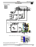
Figure 20.
Electrical connection access.
Figure 19.
Wiring diagram for P38DF with SIT Proflame Electronic Ignition
REMOTE
Receiver 14
Pin Connector
Pilot
(CPI / IPI MODE
MOTOR
IPI/CPI
RECEIVER
SPLIT FLOW
ON / OFF
TH
TPTH
DC SUPPLY
GROUND
885 Valve
Orange
Green
Chassis
connection
Remote control
Not Used)
Battery
Holder
4 x 1.5V
AA Type
120 Vac INPUT
7.5V DC
Output
Receiver 14
Battery Holder
w/ Switch
ON/REMONTE/OFF
(Not Used)
Receiver 14
Battery Holder
Top View
AC
Adapter
Green
Blk
Wht
Blk
Blk
Blk
Blk
Wht
Wht
Thermo
Sensor
Fan
Fan
Fan
Receptacle
Wht
Blk
Bulbs
Blk
Wht
Control Valve
Receptacle
Green
Green
Blk
Wht
Fan Speed
Control
Wh
t
Blk
L2
L1
Ground
Red
White
Green
Red
Black
WALL SWITCH
1
6
1
6
Power Supply
110VAC, 5amp

