background image

Page 7

P38DF* Indoor Gas Fireplace

XG0193 -103111.1

Installation

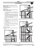
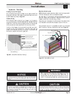
Clearances


When  installing  a  shelf  over  the  top  of  the  fireplaces,  the  following 

guidelines must be adhered to:  
For Rear Vent applications, the minimum clearance is 0" from the rear 

of the fireplace to a wall, or any combustible materials, and 9" clearance 

from the top of the fireplace to the underside of any combustible shelf 

materials. 
For Top Vent applications, the minimum clearance is 0" from the rear of 

the fireplace to a wall, or any combustible materials, and 17 1/2" to the 

underside of any combustible shelf materials. 

1” clearance is maintained on sides and bottom of vent runs and 2” 

above horizontal vent runs to any combustible material.

MODEL

Top - Rear vent


Top - T

op vent 

Rear

Sides

Floor

Mantel

P38DF*

9"

17 1/2"

0"

0"

0"

4"


nOTE: 

Clearance from top of fireplace to a combustible ceiling within 

the fireplace enclosure. 

Figure 7c.


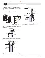
Securing the Nailing Flange Extension.

The supplied nailing extension must be placed along the top edge of 

the fireplace and securely fastened into place, as shown in 

figure 7c

Note: The nailing flange extension can be substituted with a piece of 

nOn-Combustible

 material of the same size and thermal characteristics, 

ie: cement board or equivalent.

4"

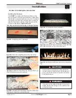
Before installing the supplied nailing flange extension, fold tabs at bottom 

of nailing flange to a 90 degree angle.

Figure 7.


Bottom of Nailing Flange Extension

Figure 7a.


Bottom of Nailing Flange Extension with tab folded at 90 

degree angle

Figure 7b.


Insert folded tabs into slots above the front of the fireplace

Front of nailing Flange

Front of Fireplace

Installing the nailing Flange Extension


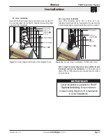
Installing The Standoffs

To  avoid  elevated  mantel  temperatures,  all 

P38DF* 

gas 

fireplaces  are  required  to  have  the  supplied  standoffs  installed. 

The fireplace is supplied with two standoffs. Bend and install these 

standoffs on top of the fireplace ensuring that the height of the standoff 

maintains a 7 1/2" clearance.

7½”

Figure 6.


Installing standoffs

Summary of Contents for P38DF Prestige Series

Page 1: ...Optical radiation Non ionizing radiation Radiation Hazardous to the Environment Danger of harming your hands Irritant Cutting Watch your step Slippery floor High temperatures Glass hazard Danger of suffocation High voltage Toxic Flammable materials Corrosive Fork lift trucks Danger overhead crane Explosion risk Oxidising Danger of death Biohazard Laser Radiation Danger of entrapment Hot surface Ge...

Page 2: ...ling Wall Mounted Direct Vent Termination 10 Section 3 3 1 Venting Layout Wall Mounted Termination 11 13 Section 3 3 2 Venting Components 14 Section 3 3 3 Heat Shields 15 Section 4 Wiring 16 SIT IPI Wiring 16 Fan Lights Wiring 16 Section 5 Installing the Gas Line 17 Section 5 1 Fuel Conversion 17 Section 5 2 Gas Pressure 17 Section 5 3 Gas Connection 17 Section 6 Finishing 18 Finishing Around the ...

Page 3: ...s being installed This installation operation and maintenance manual is applicable to the models described to the right Refer to your rating plate to verify included options Warranty and Installation Information See Appendix B The Montigo warranty will be voided by and Montigo disclaims any responsibility for the following actions Modification of the fireplace and or components including Direct Ve...

Page 4: ...bethehighestpoint in the Direct Vent installation Should it be impossible to meet the venting requirements laid out in Section 3 Venting please contact a local Montigo dealer regarding the use of a Montigo Power Vent LayouttheVentrun calculatingtherequiredelbowsandstraight runs of 5 8 flex or rigid pipe Layout Electrical Requirements Refer to Section 4 Wiring for Details Refer to Section 5 Install...

Page 5: ... be installed in any location that maintains properclearancestoairconditioningducts electricalwiringandplumbing Safety as well as efficiency of operation should be considered when selecting the fireplace location Try to select a location that does not interfere with room traffic has adequate ventilation and offers an accessible path for Direct Vent installation The fireplace dimensions are shown b...

Page 6: ...e for Natural Gas only Figure4 CombustibleFramingforshelvesoverthefireplace Top vent Figure3 CombustibleFramingforshelvesoverthefireplace Rearvent Note RearventavailableforNaturalGasonly 7 8 1 2 0 clearance to corners 3 7 3 4 55 1 2 MIN 96 12 door opening 3 Rear Vent Ceiling Floor Alcove area over Fireplace Top Vent N G L P 12 max Non combustible header Min 1 REAR VENT N G ONLY Non Combustible Mat...

Page 7: ...igure 7c Securing the Nailing Flange Extension The supplied nailing extension must be placed along the top edge of the fireplace and securely fastened into place as shown in figure 7c Note The nailing flange extension can be substituted with a piece of NON Combustiblematerialofthesamesizeandthermalcharacteristics ie cement board or equivalent 4 Beforeinstallingthesuppliednailingflangeextension fol...

Page 8: ...llar Flue Gasket Flue Cover Plate Flue Gasket Flue Cover Plate 8 Outer Flue Collar 5 Inner Flue Collar Montigo supplies a variety of direct venting and termination options The direct vent termination location MUST be selected such that it is the highest point in the venting assembly It should also be selected such that it provides the shortest vent run possible Should it be impossible to ensure th...

Page 9: ... mounted VENTING LAYOUT Selection of components and details of venting lay out should adhere to the following guidelines Themaximumterminationpointis32 abovethefireplace NOTE if the maximum termination height is used the flame pattern may be affected TheVerticalterminationmustbeaminimum2 higherthanwhere the termination exits the roofing materials asphalt shingles cedar shakes etc This distance sho...

Page 10: ...Page 10 P38DF Indoor Gas Fireplace XG0193 103111 1 Installation Figure 9c Rear vent Roof mounted venting 1 90 bend Support ring Support plate 32 max Termination 12 Max PVTK1 PEXT Sections ...

Page 11: ... Frame the BSR opening to 12 x 12 2 Secure the BSR Frame to the exterior sheathing of the structure 3 Fasten the termination to the BSR Frame using a minimum of 4 screws 1 Frame the MOSR opening to 12 x 12 2 Fasten the MOSR frame to the interior side of the studs concrete or finished wall construction using a minimum of 4 screws 3 Insert the termination into the MOSR frame as shown here from the i...

Page 12: ...idelines Vent terminations must not be recessed in walls or siding For Heat Shield requirements see Section 3 3 3 on page 16 Once the proposed venting layout has been determined refer to Figure 12 12a 15 or 15a to ensure the layout is acceptable Notes Wall Mounted Terminations TOP VENT All measurements for vertical or horizontal runs are measured from center of the vent pipe Venting runs must fall...

Page 13: ...on Use a PTO 4 termination and an PFL 1 or PFL 2 12 or 24 compressed length and a frame if appropriate Flex may be turned to obtain desired degree of angle required but must not exceed 45 Note Through the wall venting kits are also available for both the Straight and the Corner Installation The Kit includes a heat shield a PFL 18 f f flexible pipe and a termination with or without a mounting frame...

Page 14: ...8 this would be an acceptable installation Example B Unacceptable Installation If the vertical dimension from the hearth is 36 and the horizontal run to the wall flange of the vent termination is 84 this would not be an acceptable installation Example C Unacceptable Installation If the vertical dimension from the floor of the fireplace is 60 and the horizontal run to the wall flange of the vent te...

Page 15: ...consult your Building Envelope Engineer or Waterproofing Consultant for further recommendations Section 3 3 2 VENTING COMPONENTS The following components and associated Montigo part numbers for installation of a roof or wall mounted termination Use only Montigo Vent Components Use of non Montigo parts will VOID the warranty and may impede operation of the fireplace Use any combination of rigid and...

Page 16: ... to the fireplace Then fasten the vent pipe to the back of the fireplace with a minimum of three sheet metal screws From the outside slide the RHS101 outer section on see Figure 18 To complete the installation fasten the Heat Shield Outer Section Termination frame to the structure Figure 18a Figure 17 RHS8 Installation Install by sliding over vent pipe where it passes through the combustible const...

Page 17: ...4 Pin Connector Pilot CPI IPI MODE MOTOR IPI CPI RECEIVER SPLIT FLOW ON OFF TH TPTH DC SUPPLY GROUND 885 Valve Orange Green Chassis connection Remote control Not Used Battery Holder 4 x 1 5V AA Type 120 Vac INPUT 7 5V DC Output Receiver 14 Battery Holder w Switch ON REMONTE OFF Not Used Receiver 14 Battery Holder Top View AC Adapter Green Blk Wht Blk Blk Blk Blk Wht Wht Thermo Sensor Fan Fan Fan R...

Page 18: ... check pressures control valves have a provision to remove a 1 8 N PT plug to be fitted with a hose barb Q Q Montigo requires a service shut off valve be located in an accessible location to isolate the gas supply Q Q Only install gas shut off valves approved for use by the state province or other governing body in which the fireplace is being installed Section 5 3 GAS CONNECTION Q Q See Figure 21...

Page 19: ...ccess to retainers for removal of glass door Glass doors on gas fireplaces are extremely hot while the fireplace is on and remain hot even after the fireplace has been turned off Safety screens are available and can reduce the risks of severe burns Please keep children away from the fireplace at all times CAUTION Do not use ammonia based or abrasive cleaners on the glass they will permanently etch...

Page 20: ...g the Door 2 Step 5 Ensure the tool is firmly in the lower end of the slot asshown Thenpulltoward you Caution hold the tool securely 3 Step 6 Pull hard if necessary to release the spring tension Caution The latch springs backwithforce holdthetool securely 4 Step 7 Remove the tool from the latch slot Ensure the latches are hanging freely the hook end is released from the bottom of the door Repeat a...

Page 21: ... the pan and the burners as described in Figure 25 to 25f Note Only cover the burner with one layer of designer firestones Figure 25b Installation of the firestones Ensure ONLY one layer of firestones cover the surface Figure 25c Spreading the firestones evenly and make sure there are no firestones covering the pilot Figure 25d Completed firestone installation Figure25e Completed firestone install...

Page 22: ...he floor What To Do If You Smell Gas Q Q Do not try to light any appliance Q Q Do not touch any electrical switch do not use any phone in your building Q Q Immediately call your gas supplier from a neighbour s phone Follow the gas supplier s instructions 1 STOP Read the safety information above on this label 2 Remove the lower Horizontal access panel 3 Turn Incoming gas valve to the ON position 4 ...

Page 23: ...some smoke and a visible film may be left on the glass This is a normal condition and is the result of burning of protective coatings on new metal Glass must be cleaned periodically to remove any film which is a normal by product of combustion which may be visible Film can easily be removed by removing the door as shown on Page20 Handlethedoorcarefully andcleanitwithnonabrasive glass cleaners One ...

Page 24: ...r Rod Assembly RGC3053 Burner Contact Dealer NG Burner Orfice R0R1150 LP Burner Orfice R0R1157 Pilot Tubing 18 RPTA03 Control Module RGC3035 Wiring Harness RGC3041 DC Adapter RGC3043 Door Assembly RDTP52 If your fireplace still does not operate correctly consult your local Montigo dealer All service and repairs should be performed by a qualified Technician All spare parts optional fans and optiona...

Page 25: ...iance 100 000 BTU H 30 KW 12 inches 12 inches M clearance to forced air supply inlet 6 feet 3 feet above air inlet N clearance above paved sidewalk or paved driveway located on public property 7 feet 7 feet P clearance under veranda porch deck or balcony 22 inches to combustibles 16 inches to non combustibles 22 inches to combustibles 16 inches to non combustibles Q clearance above roof 2 feet 2 f...

Page 26: ...mpanies 2 The Montigo Gas Appliance must be subjected to normal use The Gas Appliances are designed to burn gas only Burning conventional fireplace fuels such as wood coal or any other solid fuel will cause damage to the Gas Appliance will produce excessive temperatures and will result in a fire hazard Limitations On Liability It is expressly agreed and understood that The Companies sole obligatio...

Page 27: ...ht of eight 8 feet above grade directly in line with the exhaust vent terminal for the horizontally vented gas fueled heating appliance or equipment The sign shall read in print size no less than one half 1 2 inch in size GAS VENT DIRECTLY BELOW KEEP CLEAR OF ALL OBSTRUCTIONS 4 INSPECTION The state or local gas inspector of the side wall horizontally vented gas fueled equipment shall not approve t...

Page 28: ...Ferndale Washington TF 1 800 789 6236 FX 1 866 3000 0927 XG0193 103111 1 Langley British Columbia TF 1 800 378 3115 FX 1 604 607 6462 P38DF Single Sided Gas Fireplace ...

Reviews: