Page 7
P52DF* Indoor Gas Fireplace
XG0196 - 150204.3
Installation
Section 2: Framing & Clearances
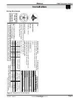
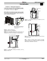
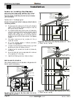
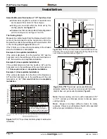
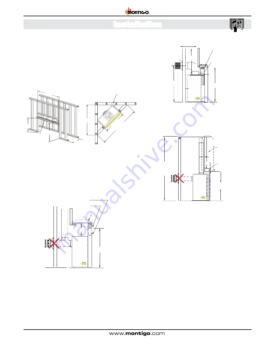
Figure 2.
Framing dimensions
(Straight wall & Corner Installation).
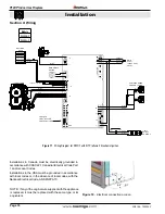
NOTE
: Non-combustible header must be installed after unit
installation and before the installation of .nailing flange.
Figure 5.
Non Combustible Framing for Top Vent or Rear
Vent, with alcove.
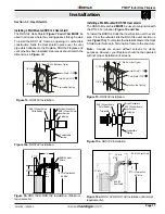
Figure 3.
Combustible Framing for shelves over the
fireplace, Rear vent.
98
”
1" clearance
to corners only
5
2”
69 1/4”
84”
Min.
Header
MIN
1”
Alcove
area over
Fireplace
Top
Vent
Non-Combustible
Materials Only
Ceiling
37
½”
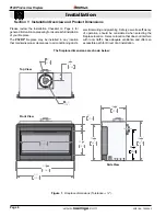
Frame in the enclosure for the unit with framing materials.
The framed opening for the assembled fireplace is 52" wide,
x 43" high x 24 1/2" deep, see
Figure 2
.
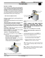
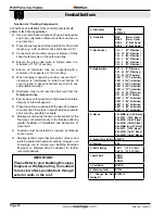
NOTE:
When constructing the framed opening, please
ensure there is access to install the gas line when the
unit is installed. See
Figure 21
.
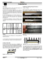
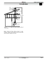
Figure 4.
Combustible Framing for shelves over the
fireplace, Top vent.
24 1/
2”
52 ”
43”
Noncombustible
Stud
37½”
Note: When sheetrock is not used behind
the fireplace, framing depth 24 1/2" may
be reduced by 5/8".
12”
Combustible Header
shelf
R
ea
r Vent
43”
Non-combustible Header
T
op V
ent
56” Min.
26” Min
43”
1”
Non-
combustible
Header
Combustible Header
1”
7”
20” Max
Heat Sheild
6 1/2”
Note:
Images are shown without screens for clarity
purposes. However, your fireplace should not be operated
without proper installation of screens.

