background image

The install requirements of your fireplace are dependent on several 

factors. Gas line location, electrical connection, gas line type and 

decorative surround options can play into the install. These factors 

should be considered when determining framing and layout of 

your fireplace.

Note:

 four sided surrounds will require a raised installation.

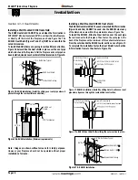
Frame in the enclosure for the unit with framing materials. The 

framed opening for the assembled fireplace is 42" wide, x 42" high 

x 21 7/8" deep, see  Figure 2

.

NOTE: When constructing the framed opening, please ensure 

there is access to install the gas line when the unit is installed. 

See Figure 21.

Figure 2. 

  Framing  dimensions,  (Straight  wall  &  Corner 

Installation). 


Note: When sheetrock is not used 

behind the fireplace, framing depth 21 

7/8" may be reduced by 5/8".

Figure 5.

 Non Combustible Framing for Top Vent or Rear 

Vent, with alcove. 

Figure 4.

 Combustible Framing for shelves over the fireplace, 

Top vent. 

Figure 3. 

Combustible Framing for shelves over the fireplace, 

Rear vent. 

42”

9”

34 1/2”

Combustible Header

Combustible Shelf

27 1/2”

 12”


max.


Non Combustible 

Stud 1/2” Above Top 

RHS101

21 7/

8”

42  ”

42”

Noncombustible 

Stud

35”

84 1/2

0" clearance

to corners 

42”


59 3/4”

40 1/2”

MEL Short
90° elbow 

50 1/2”


17 1/2”

Combustible Header

Combustible Shelf

RHS101

Non Combustible
Stud 1/2” above top

Note:  Images are shown without screens for clarity purposes. 

However, your fireplace should not be operated without proper 

installation of screens.

Non-Combustible

Materials Only

MIN

 96”

10.5”


  door

opening

3”


Rear

Vent

Ceiling

Floor

Alcove

area over

Fireplac e

Top Vent

N.G. & L.P.

12”  

max.

Non-combustible

header

Min 1”

Page 8

PL42DF* Indoor Gas Fireplace

XG0217 - 160215.1

Installation

Section 2:  Framing & Clearances

Summary of Contents for PL42DF

Page 1: ...d Optical radiation Non ionizing radiation Radiation Hazardous to the Environment Danger of harming your hands Irritant Cutting Watch your step Slippery floor High temperatures Glass hazard Danger of suffocation High voltage Toxic Flammable materials Corrosive Fork lift trucks Danger overhead crane Explosion risk Oxidising Danger of death Biohazard Laser Radiation Danger of entrapment Hot surface ...

Page 2: ... Installation 20 Section 5 Installing the Gas Line 21 Section 5 1 FUEL CONVERSION 21 Section 5 2 GAS PRESSURE 21 Section 5 3 GAS CONNECTION 21 Section 6 Finishing Around the Fireplace 22 Section 7 Screen Installation and Removal 23 Section 8 Installing Removing the Door 24 Section 9 Installing the Accessories 25 Installing the Firestones 25 Installing Optional Speckled Stones 26 Installing the Dri...

Page 3: ...iding you with a gas fireplace that is not only a beautiful addition to your space butthatisalsodesignedandmanufacturedtothehighestsafety reliability and engineering standards Westronglyencourageyoutoreadandcarefullyfollowtheinstructions laid out in this Installation Operation and Maintenance Manual and retain it for your future reference Pay special attention to all cautions warnings and notices ...

Page 4: ...nes for installation requirements Installation and repairs should be done by a qualified contractor and must conform to Installations in Canada must conform to the local codes or in the absence of local codes to the current version of Natural Gas and Propane Installation Code CSA B149 Electrical Installations must conform to the local codes or in the absence of local codes to the current version o...

Page 5: ... and sealed in compliance with local building code Terminations installed and sealed in compliance with local building code Direct vent termination is highest point in vent assembly Wiring Electrical Section 4 Unswitched power provided to the appliance PPO box Low voltage wire connected to dry contact wall switch non powered Gas Section 5 Proper appliance for fuel type Was a conversion performed L...

Page 6: ...g place may be found under the firebox To access remove the screen and valve cover See Section 7 Screen Installation and Removal and Section 8 Installing Removing the Door Page 6 PL42DF Indoor Gas Fireplace XG0217 160215 1 Installation LB1223 V5 2 SIT IPI with screen AUG 17 2015 Teklynx LabelView Demo ...

Page 7: ...ould be consideredwhenselectingthefireplacelocation Selectalocation that does not interfere with room traffic has adequate ventilation and offers an accessible path for Direct Vent installation The fireplace dimensions are shown below 42 1068 30 1 2 776 39 1 2 1004 20 1 4 515 4 3 4 121 5 1 2 140 12 5 8 320 43 5 8 1107 41 1 2 1054 23 1 8 586 5 127 8 203 12 5 8 320 34 5 8 880 20 5 8 524 21 1 4 541 2...

Page 8: ...g depth 21 7 8 may be reduced by 5 8 Figure 5 Non Combustible Framing for Top Vent or Rear Vent with alcove Figure4 CombustibleFramingforshelvesoverthefireplace Top vent Figure3 CombustibleFramingforshelvesoverthefireplace Rear vent 42 9 34 1 2 Combustible Header Combustible Shelf 27 1 2 12 max Non Combustible Stud 1 2 Above Top RHS101 21 7 8 42 42 Noncombustible Stud 35 8 4 1 2 0 clearance to cor...

Page 9: ...aceissuppliedwithtwostandoffs Bendandinstallthese standoffs on top of the fireplace ensuring that the height of the standoff maintains a 7 1 2 clearance 7 Figure 6 Installing standoffs NOTE Clearance from top of fireplace to a ceiling within the fireplace enclosure Four sided surrounds require a raised installation Figure 7c Securing the Nailing Flange Extension The supplied nailing extension must...

Page 10: ...ionMUSTbeselectedsuchthatitis thehighestpointintheventingassembly Itshouldalsobeselected such that it provides the shortest vent run possible Should it be impossible to ensure that the termination is the highest point or to meet the venting guidelines laid out below please contact your Montigo dealer to discuss power venting options NOTES FOR PLANNING VENTING Venting can originate from the unit th...

Page 11: ...emaximumterminationheightisused theflame pattern may be affected The Vertical termination must be a minimum 2 higher than where the termination exits the roofing materials asphalt shingles cedar shakes etc This distance should be measured from the high side of the roof slope where the flue flashing intersects the roofing materials see Figures 9 to 9c Terminationlocationmustbeaminimum6 fromamechani...

Page 12: ...upport plate 32 max Termination 12 Max PVTK1 PEXT Sections Note Images are shown without screens for clarity purposes However your fireplace should not be operated without proper installation of screens Page 12 PL42DF Indoor Gas Fireplace XG0217 160215 1 Installation ...

Page 13: ...e exterior sheathing of the structure 3 Fasten the termination to the BSR Frame using a minimum of 4 screws 1 Frame the MOSR opening to 12 x 12 2 Fasten the MOSR frame to the interior side of the studs concrete or finished wall construction using a minimum of 4 screws 3 Insert the termination into the MOSR frame as shown here from the inside and attach to the MOSR by installing a min quantity of 4...

Page 14: ...ion Selectionofcomponentsanddetailsofventinglayoutshouldadhere to the following guidelines Vent terminations must not be recessed in walls or siding For Heat Shield requirements see Section 3 3 3 on page 18 Oncetheproposedventinglayouthasbeendeterminedrefer to Figure 12 12a or 14 to ensure the layout is acceptable Notes Wall Mounted Terminations TOP VENT Allmeasurementsforverticalorhorizontalrunsa...

Page 15: ...ent termination is 138 this would be an acceptable installation Example B Unacceptable Installation If the vertical dimension from the hearth is 48 and the horizontal run to the wall flange of the vent termination is 72 this would not be an acceptable installation Example C Unacceptable Installation If the vertical dimension from the floor of the fireplace is 60 and the horizontal run to the wall ...

Page 16: ...reddegreeofanglerequiredbutmustnotexceed45 Note Through the wall venting kits are also available for both the Straight and the Corner Installation The Kit includes a heat shield a PFL 18 f f flexible pipe and a termination with or without a mounting frame PEL 45 Elbow PEL 90 Elbow PXT 18 IMPORTANT Corner Installation is available for PL42DF Top Vent Units Only Ensure minimum Vertical Venting Heigh...

Page 17: ...onsultant for further recommendations Section 3 3 2 Venting Components The following components and associated Montigo part num bers for installation of a roof or wall mounted termination Use only Montigo Vent Components Use of non Montigo parts will VOID the warranty and may impede operation of the fireplace Useanycombinationofrigidandflexpipeasrequiredandin any orientation Male connectors can fa...

Page 18: ...eters shown figure 16a To install the RHS101 Slide the Inner Section over the vent pipe that will connect to the fireplace Then fasten the vent pipe to the back of the fireplace with a minimum of three sheet metal screws From the outside slide the RHS101 outer section on see Figure 17 To complete the installation fasten the Heat Shield Outer Section Termination frame to the structure Figure 17a Fi...

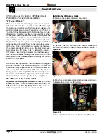
Page 19: ...type 1 5V AA type 1 5V AA type 1 5V AA type BLACK WHITE BLACK WHITE GREEN VARIABLE SPEED COMFORT FANS MAIN Power 120VAC 60 Hz 6 Amps SPARK SENSOR RED BLACK BATTERY PACK MAIN ON OFF SWITCH YELLOW GREEN 885 PROFLAME PILOT BURNER ORANGE GREEN BLACK BROWN YELLOW ORANGE 6 10 4 6 3 4 Blk Blk Wht Wht CPI IPI SWITCH BLUE WHITE X10 X11 X12 X13 X1 X6 X5 X4 X3 X2 LED Lights LED1 Red LED LED2 Amber LED 3 15A ...

Page 20: ...tially recovered as heat into the building so it does not waste as much energy as running a pilot in the off season A connector is supplied with this unit that can be plugged into the controller This Jumper Cable gives the Remote Control the ability to operate the CPI IPI switch and set the unit to operate in either condition CPI means Continuous Pilot Ignition or Standing Pilot as it is commonly ...

Page 21: ...ol valves have a provision to remove a 1 8 N PT plug to be fitted with a hose barb Montigo requires a service shut off valve be located in an accessible location to isolate the gas supply Onlyinstallgasshut offvalvesapprovedforusebythestate province or other governing body in which the fireplace is being installed Section 5 3 GAS CONNECTION See Figure 21 for location of gas line access Flexible ga...

Page 22: ...AUTION Do not use ammonia based or abrasive cleaners on the glass they will permanently etch the surface Use an approved gas fireplace glass cleaner such as Kel Kem or White off NOTICE We recommend careful consideration be given to the effects of elevated mantel temperatures which may be in excess of product design for example candles plastic or pictures This can cause melting deformation discolor...

Page 23: ...Tabs are held Place the screen in a safe place To Install Screens Hold the screens at an angle away from the fireplace and locate the Screen Bottom Tabs at the lower corners of the screen Place the screen into the Screen Tab Receptacles in the lower section of the fireplace Makesurethetabsandscreensareloweredallthewaydown intotheScreenTabReceptaclesonthefireplace Then push each Upper Screen Stud o...

Page 24: ...ard you Caution holdthetool securely 3 Step 6 Pull hard if necessary to release the spring tension Caution The latch springs back with force hold the tool securely 4 Step 7 Remove the tool from the latch slot Ensure the latches are hanging freely the hook end is released fromthebottomofthedoor Repeat all 4 steps for the remaining latches Figure 23c Figure 23d Figure 23e Door Latch Hook Door Latch ...

Page 25: ...vious steps shown in reverse order Installing the Door Step 8 GrasptheDooroneitherside usuallymidwayandliftupward liftthedoorcarefullyupandawayfromthefrontofthefireplace See Figures 23f Place the Door aside in a safe place while maintenance and or cleaning is being performed Figure 23f Removing and installing the glass doors Removing the Door WARNING When installing the fireplace gas lines fitting...

Page 26: ...e is in operation and should not be handled until cool Figure24c Completed firestone installation Note DO NOT place ANY firestones on top of the pilot cover Figure 24d Gas fireplace with firestones CAUTION If the pilot cover is covered with firestones it may result in delayed ignition and or damage to the appliance and or surrounding property WARNING WARNING This appliance is intended for use only...

Page 27: ...rom LGS58 on top of log 2 see Figure 26c 2 1 5 LGS59 1 2 3 4 5 6 The PL42DF has the option of installing a drift wood log set Once the firestones or speckled stones have been installed the log set can be installed Ensure logs are securely placed and will not tip or fall Remove media where logs touch the burner tray to ensure a more secure position Lean the logs against the back panels NO LOGS SHOU...

Page 28: ...ross log 4 from LGS58 and log 4 from LGS59 see Figure 26j 6 Step 11 Watch for sooting for 30 minutes If sooting is present adjust media and or logs to eliminate Step 7 Place log 5 from LGS59 in the back left corner of the burner behind the pilot Place Log 4 from LGS58 on top of log 5 Use stones to help stabilize log 4 See Figure 26f Figure 26f Figure 26g Figure 26h Figure 26i Figure 26j Figure 26k...

Page 29: ...emove the lower Horizontal access panel 3 Turn ON manual ON OFF switch located below the hori zontal access panel if available 4 Turn Incoming gas valve to the ON position 5 Wait 5 minutes to clear out any gas If you smell gas STOP Follow B in the safety information above on this label If you don t smell gas go to the next step 6 Turn fireplace ON using wall switch or remote control 7 If the Firep...

Page 30: ...ey is used to turn On Off or index through Thermostat functions see Figure 27 Additionally a Key Lock feature is provided The Proflame 2 System consists of the following elements 1 Pilot Assembly 2 Proflame Gas Valve 3 Proflame 2 Control Module 4 Wiring Harness 5 Variable Speed fans optional 6 Proflame 2 remote control 7 Battery Pack 8 Manual override switch NOTE Can not be used with home automati...

Page 31: ... or F is visible to the right of the Room Temperature display Turn On the Fireplace With the system Off turn the master override switch to on and press the On Off Key on the Remote Control The Remote Control display will show some other active Icons on the screen At the same time the Control Module will activate the fireplace A single beep from the Control Module will confirm reception of the comm...

Page 32: ...room thermostat is On and the set temperature is now displayed To adjust the set temperature press the Up or Down Arrow Keys until the desired set temperature is displayed on the LCD screen of the Transmitter Smart Thermostat Remote Control Operation The Smart Thermostat function adjusts the flame height in accordance to the difference between the set point temperature and the actual room temperat...

Page 33: ...eed A single beep will confirm reception of the command Disabling Thermostat Some jurisdictions and bedroom installations require the thermostat to be disabled 1 Partially take out one battery see Figure 27j 2 Insert the battery while holding down the thermostat button The remote screen will display Clr while the button is held down See Figure 27k 3 To enable thermostat repeat steps 1 2 The remote...

Page 34: ...ction press the Mode and Up Keys at the same time Remote Control When the Remote Control batteries are low a Battery Icon will appear on the LCD display of the Remote Control see Figure 27p before all battery power is lost When the batteries are replaced this icon will disappear Control Module When the back up batteries are low a double beep will be emitted from the IFC when it receivers an On Off...

Page 35: ...ble film may be left on the glass This is a normal condition and is the result of curing of protective coatings on new metal Glass must be cleaned periodically to remove any film which is a normal by product of combustion which may be visible Film can easily be removed by removing the door as shown on Page 24 Handle the door carefully and clean it with nonabrasive glass cleaners One of the most ef...

Page 36: ...g but Pilot burner will not light 1 VerifytheInletandManifoldGasPressurearewithinacceptable limits 2 Check all connections to gas valve 3 Check connection to stepper motor if available Pilot lights but Main burner will not Light 1 Check and verify all wiring connections as per the wiring diagram 2 Verify the inlet and Manifold Pressure are within acceptable limits Pilot lights but Main burner will...

Page 37: ...lver Opaque Firestones HW1082 x 4 Accessories Optional Accessory List Fan Kit HFK50R Porcelain Panel PPL42 DGB03 Ebony Firestones HW1092 x 4 DGB04 Opal Firestones HW1106 x 4 DGB07 Melon Firestones HW1109 x 4 DGB08 Sapphire Firestones HW1110 x 4 DGB09 Ivory Firestones HW1111 x 4 DGB10 Frost Firstones HW1112 x 4 DGM21 Black Ice Fireglass HW1113 x 4 DGM23 Copper Ice Fireglass HW1143 x 4 DGM24 Platinu...

Page 38: ... forced air supply inlet 6 feet 3 feet above air inlet N clearance above paved sidewalk or paved driveway located on public property 7 feet 7 feet P clearance under veranda porch deck or balcony 22 inches to combustibles 16 inches to non combustibles 22 inches to combustibles 16 inches to non combustibles Q clearance above roof 2 feet 2 feet R clearance to adjacent walls and neighboring buildings ...

Page 39: ...nly Burning conventional fireplace fuels such as wood coal or any other solid fuel will cause damage to the Gas Appliance will produce excessive temperatures and will result in a fire hazard Limitations On Liability It is expressly agreed and understood that The Companies sole obligation and purchaser s exclusive remedy under this Warranty under any other warranty expressed or implied or in contra...

Page 40: ...tally vented gas fueled heating appliance or equipment The sign shall read in print size no less than one half 1 2 inch in size GAS VENT DIRECTLY BELOW KEEP CLEAR OF ALL OBSTRUCTIONS 4 INSPECTION The state or local gas inspector of the side wall horizontally vented gas fueled equipment shall not approve the instal lation unless upon inspection the inspector observes carbon monoxide detectors and s...

Page 41: ...Page 41 PL42DF Indoor Gas Fireplace XG0217 160215 1 Notes ...

Page 42: ...XG0217 160215 1 PL42DF Single Sided Gas Fireplace ...

Reviews: