background image

Page 2

Proflame 2 Transmitter

XG0677 - 141231

Operation

The Proflame Transmitter 2 is an integrated part of the Proflame 2 System, 

which consists of these elements:

- Proflame 2 Transmitter, to be used in conjunction with:

- Integrated Fireplaces Control (Proflame 2 IFC) 

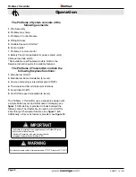
IMPORTANT

The Proflame 2 Transmitter controls the 

following fireplace functions: 

1. 

Main Burner On/Off

2.

 Main Burner flame modulation (6 levels).

3. 

Choice of standing or intermittent pilot (CPI/IPI). 

4. 

Thermostat and Smart thermostat functions. 

5. 

Accent light On/Off. 

6. 

Comfort fan speed modulation (6 levels).

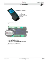
The Proflame 2 Transmitter uses a streamline design with 

a simple button layout and informative LCD display, see 

figure 1.

 A Mode Key is provided to index between the 

features and a Thermostat Key is used to turn On/Off or 

index through Thermostat functions, see 

figure 1 & 3

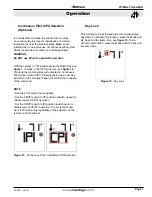
Additionally, a Key Lock feature is provided, see 

figure 15.


The Proflame 2 System consists of the 

following elements: 

1. 

Pilot Assembly

2.

 Proflame Gas Valve.

3. 

Proflame 2 Control Module

4. 

Wiring Harness

5. 

Variable Speed comfort fan *

6. 

Accent Lights *

7. Proflame 2 remote control 
8. Battery Pack (not applicable for power vented units) 
9 Manual override switch


.

WARNING

 Do not expose remote control to temperatures below 0°C (32°F) or above 50°C (122°F)


* Not available on all fireplace models. Refer to the 

fireplace instruction guide for available features.

Summary of Contents for Proflame 2

Page 1: ...ded for any length of time CAUTION Turn OFF the main gas supply of the appliance during installation or maintenance of the receiver device Turn OFF main gas supply to the appliance prior to removing ro reinserting the batteries In case of remote control malfunction turn OFF the IFC device using the On Off main switch For installation maintenance switch OFF the IFC device by removing main power sup...

Page 2: ...r uses a streamline design with a simple button layout and informative LCD display see figure 1 A Mode Key is provided to index between the features and a Thermostat Key is used to turn On Off or index through Thermostat functions see figure 1 3 Additionally a Key Lock feature is provided see figure 15 The Proflame 2 System consists of the following elements 1 Pilot Assembly 2 Proflame Gas Valve 3...

Page 3: ...on Figure 1 Proflame Remote Control Figure 2 Proflame Control Module SW1 LED1 LED2 SW1 Programing Button LED1 Red Diagnostic Light LED2 Amber Programing Remote Control Light Blue Back lit LCD display On Off Key Thermostat Key Up Down Arrow Key Mode Key ...

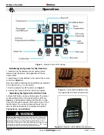
Page 4: ...mes and amber LED see figure 2 is illuminated to indicate that the IFC is ready to synchronize with a remote control within 10 sec Push the ON button The control module will beep four 4 times to indicate transmitter s command is accepted The System is now initialized Figure 4a Remote control battery compartment Battery operated device Read the battery instructions before installing them WARNING in...

Page 5: ...f the command Turn Off the Fireplace With the system On press the On Off Key on the Remote Control The Remote Control LCD display will only show the room temperature see figure 7 At the same time the Control Module will turn off the fireplace A single beep from the Receiver confirms reception of the command Figure 7 Remote Control display Remote Flame Control The proflame has six 6 flame levels Wi...

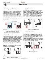
Page 6: ...ol icon see figure 12 Use the Up Down Arrow Keys see figure 1 to turn on off or adjust the fan speed see figure 12 A single beep will confirm reception of the command Figure 12 Fan Speed Control Accent Light Control The fireplace may be equipped with accent lights The auxiliary function controls the Accent Lights To activate this function use the Mode Key see figure 1 to index to the AUX icon see ...

Page 7: ...tinuous Pilot Ignition mode CPI Pressing the Down Arrow Key will return to IPI A single beep will confirm the reception of the command NOTE Requires CPI switch not supplied Set the CPI IPI switch to CPI position Switch closed to enable remote CPI IPI operation Set the CPI IPI switch to IPI position switch open to disable remote CPI IPI operation The system will now work in IPI mode only regardless...

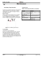
Page 8: ...of the receiver and after that no more command will be accepted When the batteries are replaced the beep will be emitted from the receiver as soon as powered Low Battery Power Detection The life span of the batteries depends on various factors quality of the batteries used the number of ignitions of the appliance the number of changes to the room thermostat set point etc Problem Solution Control m...

Page 9: ...Page 9 P52DF Indoor Gas Fireplace XG0196 141231 Notes ...

Page 10: ...XG0196 141231 Proflame 2 System ...

Reviews: